1. Reference problem#
Oscillations in contact pressures may occur in certain cases, in particular for structures where the interface intersects pentahedra, under non-uniform loading.
This is due to non-compliance with the LBB condition [bib3] [bib4]. This phenomenon of oscillations is comparable to that encountered in incompressibility [bib5]. Physically, in the case of contact, this amounts to wanting to impose contact at too many points of the interface (over-stress), making the system hyperstatic. To release it, you have to restrict the space of the Lagrange multipliers, as is done in [bib6] for the Dirichlet conditions with X- FEM. Such algorithms present P0 segments, which slow down convergence. A good algorithm should minimize the occurrence of such segments. The algorithm proposed by Moës [bib6] to reduce oscillations is adapted to the 3D case (algorithm version 1). This algorithm has been improved to make it more physical and more efficient (algorithm version 2). A comparison of the two versions is made.
It should be noted that these parasitic oscillations are not reproducible in the current version of Code_Aster: one of the two algorithms is systematically chosen (2 is used by default), and even overloading the code to use none would lead to a zero pivot. We illustrate them in this documentation with results from another formulation (formulation with edges [bib7]), which has now been resolved.
For hexahedra or quadrangles cut horizontally, there are no P0 segments.
1.1. Geometry#
The structure is a straight parallelepiped with a square and healthy base. The dimensions of the block are: \(\mathrm{LX}=5m\), \(\mathrm{LY}=20m\), and \(\mathrm{LZ}=20m\). It has no cracks [Figure 1.1-1].
The interface is introduced by level sets directly into the command file using the DEFI_FISS_XFEM [U4.82.08] operator. The interface is present within the structure through its representation by the level sets. The normal level set (\(\mathrm{LSN}\)) allows you to define a flat, non-leaning interface that completely crosses the elements, using the following equation:
\(\mathrm{LSN}=Z-17.5\) eq 1.1-1
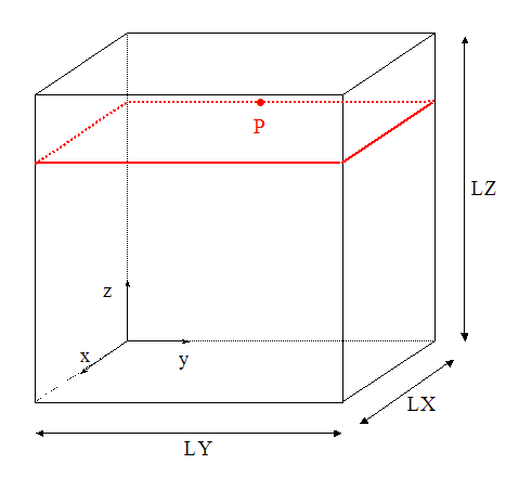
Figure 1.1-1: Interface geometry and positioning
1.2. Material properties#
Young’s module: \(E=100\mathit{GPa}\).
Poisson’s ratio: \(\nu =0\).
1.3. Boundary conditions and loads#
The underside is embedded.
The upper face is subjected to parabolic pressure whose expression is:
\(\mathrm{pression}=(100-\frac{{(Y-10)}^{2}}{2})\frac{E}{{10}^{6}}\mathrm{Pa}\) eq 1.3-1
Displacements along the \(x\) and \(y\) axes are blocked for the nodes on the upper surface.
1.4. Bibliography#
Massin P., Ben Dhia H., Zarroug M.: Contact elements derived from a continuous hybrid formulation, Code_Aster Reference Manual, [R5.03.52]
Massin P., Geniaut S.: Method X- FEM, Code_Aster Reference Manual, [R7.02.12]
Babuška I.: The finite element method with lagrangian multipliers, Numerische Math 20, 179-192, 1973
Barbosa H., Hugues T.: Finite element method with lagrange multipliers on the boundary. Circumventing the Babuška-Brezzi condition, Comp. Meth. Applied Mech Engrg. 85 (1), 109-128, 1991
Chapelle D., Bathe K.J.: The INF-Sup Test, Computers & Structures 47 (4/5), 537-545, 1993
Moës N., Béchet E., Tourbier M.: Imposing Dirichlet boundary conditions in the extended finite element method, Int. J.Numer. Meth. Engng, 2006, Vol. 67 (12), 1641-1699.
Geniaut S., Massin P., Moës N., A stable 3D contact formulation using X- FEM, European Journal of Computational Mechanics, Vol.16, No. 2, No. 2, Pages 259-276, 2007.