16. L modeling: pyramids (algorithm version 2)#
16.1. Characteristics of the mesh#
The linear element mesh consists of hexahedra, tetrahedra, and pyramids. The crack illustrated in blue on the cross crosses part of the pyramids and the tetrahedra in their middle.
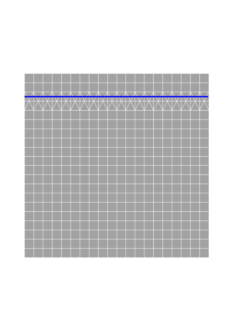
Figure 16.1-1: Meshing of hexahedra, tetrahedra, and pyramids
16.2. Tested features#
Friction is taken into account and the contact is active from the first iteration of active stresses. Unknown contact pressures are put at the nodes of the elements. The algorithm for restricting the space of Lagrange multipliers is No. 2. Here we test the pyramid elements.
16.3. Tested sizes and results#
The value of the contact pressure is tested at the point \(\mathit{P1}\) and \(\mathit{P2}\) with respective coordinates \((\mathrm{0,10}\mathrm{,17}\mathrm{.})\) and \((\mathrm{0,10}\mathrm{,18}\mathrm{.})\). These nodes are the vertices of the edge that passes through the point \(P\) \((\mathrm{0,10}\mathrm{,17}.5)\).
Identification |
Reference |
% difference |
Points \(\mathit{P1}\) and \(\mathit{P2}\) |
|
0.0351 |
16.4. Comparison curves#
The [] represents the contact pressure curves along the axis \(\mathit{Oy}\) to \(x=0\) for the A and L models. The values in \(z=17\) were taken for the M modeling since there is no step in \(z=17.5\) as for the A. It is however noted that the modeling curve L follows the reference curve obtained with the hexahedron mesh.
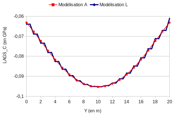
Figure 16.4-1: Comparison of contact pressures according to the models
16.5. Comments#
We find results comparable to those of modeling A where the entire mesh of the structure contains hexahedra. The introduction of pyramids into the mesh at the level of the contact surface does little to alter the contact pressure results.