2. Modeling A: hexahedra (version 2)#
In this modeling, the mesh in question only includes hexahedra. This modeling serves as a reference for the others, as this case does not present P0 segments. In fact, in the case of hexahedra cut by an interface parallel to the faces, the number of contact pressures (one per cut edge) is compatible with the discretization of the displacement field [bib1] [bib2].
2.1. Characteristics of the mesh#
The problem is invariant along the \(\mathit{Ox}\) axis. In order to limit the calculation time, the mesh considered here comprises only one element along this axis. The structure is then modelled by a regular mesh composed of \(1\times 20\times 20\) HEXA8 see [Figure 2.1-1].
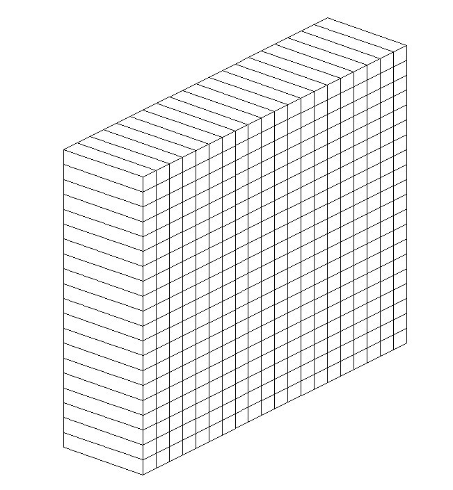
Figure 2.1-1: Hexahedron mesh
This mesh is composed of linear finite elements. In the context of the continuous [bib1] method with X- FEM [bib2], the contact unknowns are carried by the vertex nodes.
2.2. Features tested#
The integration diagram reduced to 4 Gauss points per contact facet is used.
Friction is taken into account and the contact is active from the 1st iteration of active stresses.
2.3. Tested sizes and results#
The contact pressure value is tested at point \(P\) with coordinates \((\mathrm{0,}\mathrm{10,}17.5)\). This value is used as a reference for other models.
\(\lambda =-9528440\mathit{Pa}\)