1. Introduction#
1.1. Geometry#
The study concerns a thick steel plate. Its geometry is simple. It is a simple flattened cube with the following dimensions [cf. Fig. 1.1]:
length = \(\mathrm{2,0}\) meters;
width = \(\mathrm{2,0}\) meters;
thickness = \(\mathrm{0,003}\) meters.
The plate is firmly embedded on one of its sides (ENCAS) and fixed on a vibrating table.
We want to calculate the displacement of a point located on the upper face in a corner of a plate, opposite to the embedment (point P).
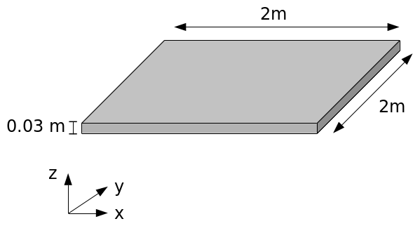
Fig. 1.1 Geometry (3D view)#
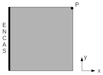
Fig. 1.2 Geometry (top view)#
1.2. Materials#
For linear analyses, steel is considered to be an isotropic, linear elastic material:
Young’s modulus: \(E\mathrm{=}200000.{10}^{+6}\mathit{Pa}\);
Poisson’s ratio: \(\nu \mathrm{=}\mathrm{0,3}\);
density: \(\rho \mathrm{=}8000\mathit{kg}\mathrm{/}{m}^{3}\).
Post-elastic (plastic) behavior is idealized by an elastoplastic law with linear work hardening whose plastic modulus (the plastic slope) is 1% of the elastic Young’s modulus. The elastic stress threshold is 200 MPa.
1.3. Boundary conditions and loading#
The plate is embedded on one of its sides.
A distracted (or somewhat facetious) engineer made a mistake in the vibrating table settings. Instead of the expected stress (a synthetic accelerogram), it sent a simple sinusoidal signal but of very high amplitude. The plate was not designed for such a shock and an attempt is being made to determine the movement that the plate may have undergone during this unfortunate test.
The input signal is a simple sine with frequency \(15\mathit{Hz}\).
The amplitude is \(\mathrm{30g}\) horizontally and \(\mathrm{30g}\) vertically downwards (\(g=10m/{s}^{2}\)).
The duration of the signal is \(0.5s\).