5. B modeling#
5.1. Characteristics of modeling#
The mass-spring systems are modelled, as in modeling A, by a discrete element with 3 degrees of freedom DIS_T.
Problem modeling 1:

Figure 5.1-a : Modeling of a mass-spring system impacting a rigid wall
Node \(\mathrm{NO1}\) is subject to an imposed acceleration \({\gamma }_{1}(t)\). We calculate the relative displacement of node \(\mathrm{NO2}\), its training displacement, and its absolute displacement.
An element of type DIST_T on a POI1 mesh is used to simulate the impact of the beam on a rigid wall: any impacts between the beam and the obstacle are taken into account as being forces internal to this element. It is assigned a non-linear shock-type behavior (stiffness) via the behavior law DIS_CONTACT of the DEFI_MATERIAU command.
The thickness of material surrounding the shock node in the direction in question is specified by the operand DIST_1 of the DEFI_MATERIAU command. In the case treated, we choose DIST_1 \(=0.4495\) and JEU \(=0.45\) so that at the initial moment, the shock node and the obstacle are separated from the game \(j=5.{10}^{-4}\mathrm{mm}\) (cf. figure).
The seismic load, due to the imposed movements of node \(\mathrm{NO1}\), is calculated by the operator CALC_CHAR_SEISME. A charge concept is then created from the VECT_ASSE operand of the AFFE_CHAR_MECA command.
We use the implicit integration scheme of NEWMARK from DYNA_NON_LINE with the keyword SCHEMA_TEMPS (FORMULATION =” DEPLACEMENT “) with a time step of \({10}^{-3}s\) and the default parameters.
Problem modeling 2:
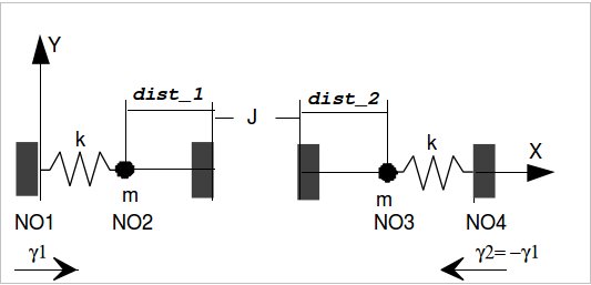
Figure 5.1-b : Modeling two mass-spring systems that collide
Node \(\mathrm{NO1}\) is subject to enforced acceleration \({\gamma }_{1}(t)\), node \(\mathrm{NO4}\) to \({\gamma }_{2}(t)=–{\gamma }_{1}(t)\). We calculate the relative and absolute displacements of the nodes \(\mathrm{NO2}\) and \(\mathrm{NO3}\), their training displacement and their absolute displacement.
Any shocks between the two beams are taken into account as being forces internal to an element with two nodes. This element is assigned a nonlinear shock-type behavior (stiffness) via the keyword RIGI_NOR of the behavior law DIS_CONTACT of the command DEFI_MATERIAU. The normal direction of contact is the local axis \(x\) of the discrete element with two nodes.
The thicknesses of material surrounding the shock nodes in the direction in question are specified by the operands DIST_1 and DIST_2 of the command DEFI_MATERIAU. In the case treated, we choose DIST_1 = DIST_2 \(=0.4495\) so that at the initial moment, the two shock nodes are separated from the game \(J=2.j={10}^{-3}m\) (cf. figure).
The seismic load, due to the imposed movements of the anchors (nodes \(\mathrm{NO1}\) and \(\mathrm{NO4}\)), is calculated by the operator CALC_CHAR_SEISME. We create a charge concept from the VECT_ASSE operand of the AFFE_CHAR_MECA command.
The time integration is carried out with the Newmark algorithm and a time step of \({10}^{-3}s\). The calculations are archived every 8 time steps.
We consider a reduced amortization \(\xi\) of 7% for all the calculated modes (keyword AMOR_MODAL of the operator DYNA_NON_LINE).
5.2. Characteristics of the mesh#
The mesh associated with the bishock model consists of 4 knots and 3 DIS_T type meshes.