2. Benchmark solution#
2.1. Calculation method used for the reference solution#
(1) The reference solution is an analytical solution resulting from, for a circular crack with radius \(a\) in an infinite medium, subject to a uniform surface force \(\sigma\) inclined at an angle \(\alpha\) to the plane of the crack, the stress intensity factors for a point \(A\) placed on the crack front are equal to: ———————————————————————–
\({K}_{I}\mathrm{=}\frac{2}{\pi }\sigma ({\mathrm{sin}}^{2}\alpha )\sqrt{\pi a}\)
\({K}_{\mathit{II}}\mathrm{=}\frac{4}{\pi (2\mathrm{-}\nu )}\sigma (\mathrm{sin}\alpha \mathrm{cos}\alpha )\mathrm{cos}\omega \sqrt{\pi a}\)
\({K}_{\mathit{III}}\mathrm{=}\frac{4(1\mathrm{-}\nu )}{\pi (2\mathrm{-}\nu )}\sigma (\mathrm{sin}\alpha \mathrm{cos}\alpha )\mathrm{sin}\omega \sqrt{\pi a}\)
\(\omega\) being the angle characterizing the position of the point \(A\) on the circular background (see).
2.2. Benchmark results#
For the load under consideration and \(a\mathrm{=}\mathrm{2m}\), the gives the analytical values of SIFs along half of the crack bottom, for \(\omega\) between \(0°\) and \(180°\). These values are also shown on the.
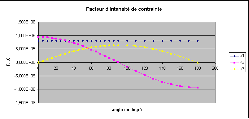
Figure 2.2-1: Reference values for SIFs
Angle \(\omega\) (°) |
\({K}_{I}\) \((\mathit{Pa}\mathrm{.}\sqrt{M})\) |
|
|
|
0 |
7,978E+05 |
9,387E+05 |
0.0E+05 |
0.0E+05 |
5 |
7,978E+05 |
9,351E+05 |
5,727E+05 |
5,727E+04 |
10 |
7,978E+05 |
9,244E+05 |
1,14E+05 |
1,14E+05 |
15 |
7,978E+05 |
9,067E+05 |
1,701E+05 |
1,701E+05 |
20 |
7,978E+05 |
8,821E+05 |
2,247E+05 |
2,247E+05 |
25 |
7,978E+05 |
8,507E+05 |
2,777E+05 |
2,777E+05 |
30 |
7,978E+05 |
8,129E+05 |
3,285E+05 |
3,285E+05 |
35 |
7,978E+05 |
7,689E+05 |
7,689E+05 |
3,769E+05 |
40 |
7,978E+05 |
7,191E+05 |
7,191E+05 |
4,224E+05 |
45 |
7,978E+05 |
6,638E+05 |
4,646E+05 |
4,646E+05 |
50 |
7,978E+05 |
6,034E+05 |
5,034E+05 |
5,034E+05 |
55 |
7,978E+05 |
5,384E+05 |
5,382E+05 |
5,382E+05 |
60 |
7,978E+05 |
4,693E+05 |
5,690E+05 |
4,693E+05 |
65 |
7,978E+05 |
3,967E+05 |
5,955E+05 |
5,955E+05 |
70 |
7,978E+05 |
3,211E+05 |
6,175E+05 |
6,175E+05 |
75 |
7,978E+05 |
2,430E+05 |
6,347E+05 |
6,347E+05 |
80 |
7,978E+05 |
1,630E+05 |
6,471E+05 |
6,471E+05 |
85 |
7,978E+05 |
8,181E+04 |
6,546E+05 |
|
90 |
7,978E+05 |
5,750E-11 |
6,571E+05 |
|
100 |
7,978E+05 |
-1,630E+05 |
6,471E+05 |
6,471E+05 |
110 |
7,978E+05 |
-3,211E+05 |
6,175E+05 |
6,175E+05 |
120 |
7,978E+05 |
-4,693E+05 |
5,690E+05 |
5,690E+05 |
130 |
7,978E+05 |
-6,034E+05 |
5,034E+05 |
5,034E+05 |
140 |
7,978E+05 |
-7,191E+05 |
4,224E+05 |
4,224E+05 |
150 |
7,978E+05 |
-8,129E+05 |
3,285E+05 |
3,285E+05 |
160 |
7,978E+05 |
-8,821E+05 |
2,247E+05 |
2,247E+05 |
170 |
7,978E+05 |
-9,244E+05 |
1,14E+05 |
1,14E+05 |
180 |
7,978E+05 |
-9,387E+05 |
8,050E-11 |
8,050E-11 |
Table 2.2-1: Reference values
2.3. Bibliographical references#
TADA H., PARIS P., IRWIND G.: The stress analysis of cracks handbook, 3rd ed., 2000
LORENTZ E., Effect of a free mesh of a cracked three-dimensional structure on the quality of the calculation of the energy restoration rate, CR-I20-2010-11, 2010