10. Keyword ORIENTATION#
10.1. Affordable characteristics#
This keyword makes it possible to assign orientations:
the main axes of the cross sections of the beam-type elements,
discrete elements assigned to nodes or meshes of type POI1 (discrete nodal elements) or to meshes of type SEG2 (discrete link elements).
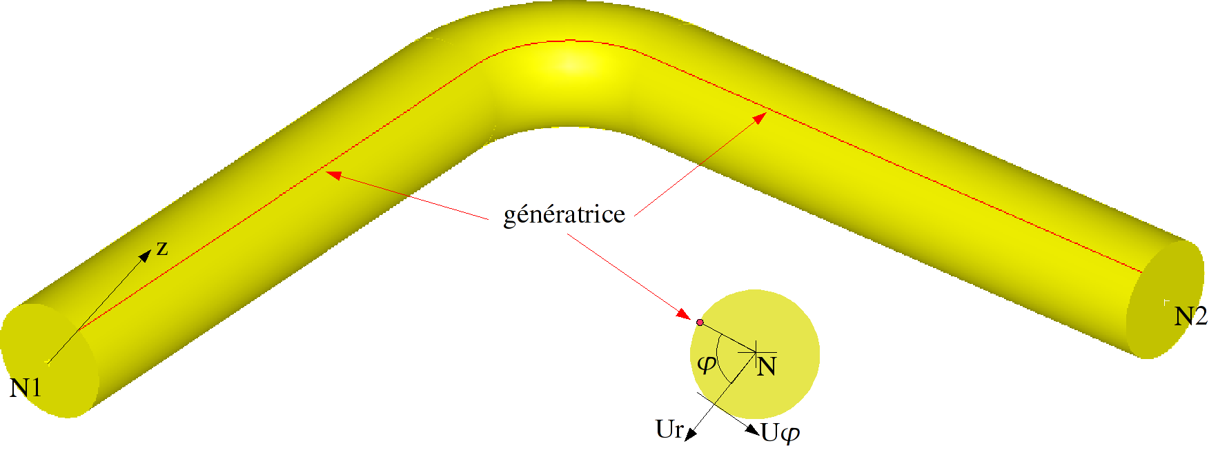
the position of the generator for the pipes elements.
For elements of type TUYAU, the ORIENTATION keyword must always be entered in order to specify a continuous generator line defining the angular origin for each section.
10.2. Syntax#
ORIENTATION = _F (
♦ CARA = [“VECT_Y”|”ANGL_VRIL”|”VECT_X_Y”|
“ANGL_NAUT”|”GENE_PIPE”],
# if CARA = “VECT_Y “
♦ VALE = vector, [3 réels]
♦ GROUP_MA = lgma, [l_gr_mesh]
◊ PRECISION = eps, [real]
# if CARA = “ANGL_VRIL “
♦ VALE = angle, [1 réel]
♦ GROUP_MA = lgma, [l_gr_mesh]
◊ PRECISION = eps, [real]
# if CARA = “VECT_X_Y “
♦ VALE = 2 vectors, [6 réels]
♦ GROUP_MA = lgma, [l_gr_mesh]
◊ PRECISION = eps, [real]
# if CARA = “ANGL_NAUT “
♦ VALE = angles, [3 réels]
♦ GROUP_MA = lgma, [l_gr_mesh]
◊ PRECISION = eps, [real]
# if CARA = “GENE_TUYAU “
♦ VALE = vector, [3 réels]
♦ GROUP_NO = lgno, [l_gr_node]
◊ CRITERION = “RELATIVE”|”ABSOLUTE” [default]
◊ PRECISION = eps (1.E-4), [real (default)]
10.3. Rules of use#
The overload rule is applied. The the orientation taken is the last affected.
Example:
ORIENTATION =(
_F (CARA = “ANGL_NAUT”, VALE = (1.0, 1.0, 1.0), GROUP_MA = “GP1”),
_F (CARA = “ANGL_VRIL”, VALE = 45.0, GROUP_MA = “GM1”),
_F (CARA = “ANGL_VRIL”, VALE = 90.0, GROUP_MA = “GM2”),
to define the local coordinate system associated with a POI1 mesh or a node (discrete element), you must use either ANGL_NAUT or VECT_X_Y,
to define the local coordinate system around the axis defined by a SEG2 mesh (beam or discrete), you must use either ANGL_VRIL or VECT_Y,
to define a generating line on pipe elements, you must use GENE_TUYAU.
Note s :
There is always a local coordinate system by default attached to elements of type POUTRE or DISCRET even if the operand ORIENTATIONis not used. It corresponds to ANGL_VRIL =0 for elements attached to a mesh SEG2 (beams or discrete) and ANGL_NAUT = \((\mathrm{0.0,}\mathrm{0.0,}0.0)\) for nodal discrete elements.
In the case where the angle \(\mathrm{\alpha }\) [figure] is either zero or undefined (as for a SEG2sur axis \(z\) ) the axis \(y\mathrm{1,}y2\) are parallel to the axis \(Y\). In this case the axis \(y3\) is by default parallel to the axis \(Y\) , because ANGL_VRIL is null by default.
10.4. Operand CARA = “ANGL_NAUT”#
♦ VALE = (\(\alpha\), \(\beta\), \(\gamma\))
The nautical angles \(\alpha\), \(\beta\), \(\gamma\), provided in degrees, are the angles used to pass from the global coordinate system for defining the coordinates of the nodes \((P,x,y,z)\) to the local coordinate system \((P,{x}_{\mathrm{3,}}{y}_{\mathrm{3,}}{z}_{3})\). This is obtained by 3 rotations:
a rotation of angle \(\alpha\) around \(Z\), turning \((x,y,z)\) into \(({x}_{\mathrm{1,}}{y}_{\mathrm{1,}}{z}_{1})\) with \({z}_{1}\equiv z\) [Figure]
a rotation of angle \(\beta\) around \({y}_{1}\), turning \(({x}_{\mathrm{1,}}{y}_{\mathrm{1,}}{z}_{1})\) into \(({x}_{\mathrm{2,}}{y}_{\mathrm{2,}}{z}_{2})\) with \({y}_{2}\equiv {y}_{1}\) [Figure]
a rotation of angle \(\gamma\) around \({x}_{2}\), turning \(({x}_{\mathrm{2,}}{y}_{\mathrm{2,}}{z}_{2})\) into \(({x}_{\mathrm{3,}}{y}_{\mathrm{3,}}{z}_{3})\) with \({x}_{3}\equiv {x}_{2}\) [Figure]
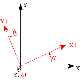
Figure 10.4-1 : angle \(\alpha\) . |
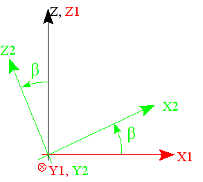
Figure 10.4-2 : angle \(\beta\) . |
Note: For the figure, rotation angle \(\beta\) is negative.
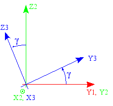
Figure 10.4-3 : angle \(\gamma\) .
The local coordinate system is: \(({X}_{3}{Y}_{3}{Z}_{3})\)
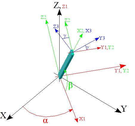
Figure 10.4-4 : Representation of global and local landmarks.
ANGL_NAUT allows you to define the local coordinate system associated with a POI1 mesh (for a discrete element). It is also possible to define the orientation of a segment, but in this case, the segment must be of zero length, because otherwise the first 2 angles are determined (cf ANGL_VRIL).
◊ PRECISION = eps
This keyword makes it possible to define the length below which the mesh is considered to be of zero size. This keyword is optional and is sometimes necessary, due to the precision of the coordinates of the nodes, in the mesh file.
10.5. Operand CARA = “VECT_X_Y”#
♦ Oval = \(\left({x}_{1}^{l},{x}_{2}^{l},{x}_{3}^{l},{y}_{1}^{d},{y}_{2}^{d},{y}_{3}^{d}\right)\)
\({x}_{1}^{l},{x}_{2}^{l},{x}_{3}^{l}\) are the 3 components, in the global coordinate system, of a vector defining the local axis \({X}_{3}\).
\({y}_{1}^{d},{y}_{2}^{d},{y}_{3}^{d}\) are the 3 components, in the global coordinate system, of a vector \({Y}^{d}\), whose projection on the plane orthogonal to \({X}_{3}\) will provide the local axis \({Y}_{3}\). The local axis \({Z}_{3}\) then completes the coordinate system so that the trihedron \(\left(P,{X}_{3},{Y}_{3},{Z}_{3}\right)\) is direct [Figure].
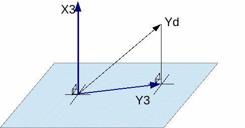
Figure 10.5-1 : Definition of VECT_X_Y .
VECT_X_Y allows you to define the local coordinate system associated with a POI1 mesh or a node (for a discrete element). It is also possible to define the orientation of a segment, but in this case, the segment must be of zero length, because otherwise the first 2 angles are determined (cf ANGL_VRIL).
◊ PRECISION =/eps
This keyword makes it possible to define the length below which the mesh is considered to be of zero size. This keyword is optional and is sometimes necessary, due to the precision of the coordinates of the nodes, in the mesh file.
10.6. Operand CARA = “ANGL_VRIL”#
♦ VALE = \(\gamma\)
In the case of mesh SEG2, the \({x}_{3}\) axis is already carried by the mesh (the meaning of \({x}_{3}\) is defined by the numbering of two nodes in the mesh, it can be changed by MODI_MAILLAGE/ORIE_LIGNE, [U4.23.04]. It is therefore possible to define \({y}_{3}\) and \({z}_{3}\) by rotating around \({x}_{3}\).
\(\gamma\) is the angle (in degrees) of rotation around \({x}_{2}\), turning \(\left(P,{x}_{2},{y}_{2},{z}_{2}\right)\) into \(\left(P,{x}_{3},{y}_{3},{z}_{3}\right)\) with \({x}_{3}\equiv {x}_{2}\) [Figure].
ANGL_VRIL allows you to define the local coordinate system around the axis defined by a SEG2 mesh (beam or discrete). The 2 angles \(\alpha\) and \(\beta\) are defined by the orientation of the segment which must therefore be of non-zero length.
◊ PRECISION = eps
This keyword makes it possible to define the length below which the mesh is considered to be of zero size. This keyword is optional and is sometimes necessary, due to the precision of the coordinates of the nodes, in the mesh file.
10.7. Operand CARA = “VECT_Y”#
♦ Oval = \({y}_{1}^{d},{y}_{2}^{d},{y}_{3}^{d}\)
In the case of mesh SEG2, the \({x}_{3}\) axis is already carried by the mesh (the meaning of \({x}_{3}\) is defined by the numbering of two nodes in the mesh, it can be changed by MODI_MAILLAGE/ORIE_LIGNE, [U4.23.04]. It is therefore possible to define \({y}_{3}\) and \({z}_{3}\) by defining a vector.
\({y}_{1}^{d},{y}_{2}^{d},{y}_{3}^{d}\) are the 3 components of a vector \({Y}^{d}\) whose projection on the plane orthogonal to \({x}_{3}\) will provide the local axis \({y}_{3}\) [Figure]. The \({z}_{3}\) axis is such that \(\left(P,{x}_{3},{y}_{3},{z}_{3}\right)\) is direct.
VECT_Y allows you to define the local coordinate system around the axis defined by a SEG2 mesh (beam or discrete). The 2 angles \(\alpha\) and \(\beta\) are defined by the orientation of the segment which must therefore be of non-zero length.
◊ PRECISION = eps
This keyword makes it possible to define the length below which the mesh is considered to be of zero size. This keyword is optional and is sometimes necessary, due to the precision of the coordinates of the nodes, in the mesh file.
10.8. Operand CARA = “GENE_TUYAU”#
♦ VALE = \(({z}_{\mathrm{1,}}{z}_{\mathrm{2,}}{z}_{3})\)
This only concerns elements TUYAU (TUYAU_3M or TUYAU_6M models).
It is appropriate to give the 3 components of a vector \(z\) orienting the generator of the pipe (solid line drawn on the pipe, defining for each element the origin of the angle \(\varphi\) used to express the ovalization and the warping).
This vector should be defined at a node or a group_no end of the pipe. The geometry is then built automatically for all the related elements in TUYAU.
When detecting the pipe line, starting from one of the end nodes, the meshes must all be oriented in the same direction. If this is not the case, an error concerning the coherence of the angles between 2 neighboring cells may be emitted.
◊ PRECISION = eps
◊ CRITERE = [“RELATIF”, “ABSOLU”] [default]
This precision is used to build the generator as well as to define the limit between a straight pipe element and a curved element (distinction based on the alignment of the 3 or 4 nodes of the element).