15. Keyword GRILLE#
15.1. Syntax#
GRILLE = _F (
    ♦ GROUP_MA = lgma, [l_gr_mesh]
    ♦/SECTION = S1, [real]
      /SECTION_FO = s1fct [function]
    ♦/ANGL_REP_1 = (:math:`\mathrm{\alpha }`, :math:`\mathrm{\beta }`) [l_real]
      /ANGL_REP_2 = (:math:`\alpha`, :math:`\beta`) [l_real]
      /VECT_1 = (vx, vy, vz) [l_real]
      /VECT_2 = (vx, vy, vz) [l_real]
    ◊/EXCENTREMENT = ez, [real]
      /EXCENTREMENT_FO = ezfct [function]
    ◊/REPERE =/"CYLINDRIQUE ",
      /"GLOBAL" (by default),
# If: (equal_to (" REPERE "," CYLINDRIQUE "," "))
    ♦/ORIGINE = l_origin, [l_real]
    ♦/AXE_Z = l_axis, [l_real]

    ◊ COEF_RIGI_DRZ = kz (1.E-10), [real (default)]
)
15.2. Affordable characteristics#
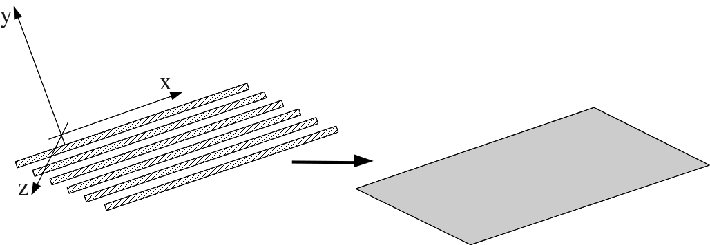
Figure 15.2-1: Replacing the frames with an equivalent sheet
Allows you to define the characteristics of a sheet characterized by stiffness in a single direction, used in particular to model reinforcement layers in reinforced concrete shells, (see for example test SSNS100 [V6.05.100]), assigned to GRILLE_EXCENTRE or GRILLE_MEMBRANE models).
To describe a « lattice » of reinforcements, it suffices to superimpose two grille_excentre or grille_membrane elements whose orientations (and therefore the rigidities) are orthogonal (see example in the next paragraph).
15.3. Description of operands#
The following geometric data are required to model the reinforcement sheet:
♦/SECTION = \({S}_{1}\)
/SECTION_F0 = \(\mathit{S1fct}\)
SECTION: reinforcing bar section in direction 1, per unit length. It therefore corresponds to the cumulative cross section over a unit width. If there is a \(s\) section for every unit \(1/\mathrm{5ème}\), the cumulative section is \(5\times s\).
SECTION_FO: function giving the section of the reinforcements in direction 1, per unit of length. It therefore corresponds to the cumulative cross section over a unit width. This function depends on geometry \((X,Y,Z)\) and is evaluated at the center of gravity of the mesh.
◊/EXCENTREMENT = \({e}_{z}\)
/EXCENTREMENT_F0 = \(\mathit{ezfct}\)
EXCENTREMENT: value of the \({e}_{z}\) eccentricity (constant for all the nodes of the mesh) of the reinforcement sheet in relation to the support mesh (distance measured on the normal of the support mesh), (modeling GRILLE_EXCENTRE only).
EXCENTREMENT_F0: function that gives the eccentricity (constant for all the nodes of the mesh) of the reinforcement sheet in relation to the support mesh (distance measured on the normal of the support mesh), (modeling GRILLE_EXCENTRE only). This function depends on the geometry (X, Y, Z) and is evaluated at the center of gravity of the mesh.
◊ COEF_RIGI_DRZ = see keyword COQUE [§8].
◊/REPERE =/ »CYLINDRIQUE « ,
/ »GLOBAL » (by default),
Using VECT_1/VECT_2 is easy and convenient. However, it is not always possible to use them as in the case of a polar coordinate system in a horizontal plane. The REPERE option is by default equal to « GLOBAL » but the user can specify a « CYLINDRIQUE » coordinate system by specifying ORIGINE and AXE_Z. In this case, VECT_1 and VECT_2 (but also ANGL_REP_1 and ANGL - REP_2) will be expressed in this cylindrical coordinate system.
# If: (equal_to ( » REPERE « , » CYLINDRIQUE « , » « ))
♦/ORIGINE = (x, y, z),
ORIGINE defines the coordinates in the global coordinate system of the center of the « CYLINDRIQUE » coordinate system.
♦/AXE_Z = (vx, vy, vz),
AXE_Z defines in the global coordinate system the vector according to the height of the « CYLINDRIQUE » coordinate system.
♦/ANGL_REP_1 = see ANGL_REP for the shell keyword [§8].
This keyword makes it possible to define the reference axis \(x\) of the local coordinate system from two nautical angles. It also defines the coordinate system in which deformations, stresses, curvatures, etc. are calculated.
/ANGL_REP_2 = see ANGL_REP for the shell keyword [§8].
This keyword makes it possible to define the reference axis \(y\) of the local coordinate system from two nautical angles. It also defines the coordinate system in which deformations, stresses, curvatures, etc. are calculated.
/VECT_1 = (vx, vy, vz)
This keyword also makes it possible to set the local coordinate system for the element. The projection of the vector entered using the keyword VECT_1 defines the local \(x\) vector.
/VECT_2 = (vx, vy, vz)
This keyword also makes it possible to set the local coordinate system for the element. The projection of the vector entered using the keyword VECT_2 defines the local \(y\) vector. For example, in the case of cylindrical geometry, it makes it possible to define the directions of the circumferential reinforcements.
To define a grid containing reinforcements in the longitudinal direction and in the transverse direction, it is necessary to create two layers of elements (crea_mesh command, keyword crea_group_ma), an element layer for the longitudinal direction and a second layer of elements for the transverse direction:
GRILLE =(
_F (GROUP_MA = “GEOL”,
SECTION = 0.02,
ANGL_REP_1 = (0.0, 0.0,),
EXCENTREMENT = 0.0,
),
_F (GROUP_MA = “GEOT”,
SECTION = 0.01,
ANGL_REP_1 = (90.0, 0.0,),
EXCENTREMENT = 0.01,
),