6. Mesh#
Creation, modification, deletion, and assignment of the properties of mesh.
6.1. Mesh criteria definition#
# |
|
Step actions |
Add a new meshing property. |
Instruction |

|
Expected results |
Arow is added in the Mesh Properties table. By default, it isassigned to the whole structure and thus he Assigned box is in green. The gear should also be green since the default meshing criteria are valid. |
Execution |
Manual |
# |
|
Step actions |
Fill in the information of the input window with invalid value. |
Instruction |

Element size: -0.2m |
Expected results |
The box with invalid input is colored in red and it is not possible to save the information and close the dialog |
Execution |
Manual |

# |
|
Step actions |
Fill in the information of the input window with valid value. |
Instruction |
Element size: 0.2m - Click on save button |
Expected results |
Meshing criterion (element size) is changed. |
Execution |
Manual |
# |
|
Step actions |
Delete a meshing property. |
Instruction |
|
Expected results |
Mesh property is deleted. |
Execution |
Manual |
# |
|
Step actions |
Hover the mouse over the assign box in the Mesh Properties table (Table View). |
Instruction |
|
Expected results |
A list of the assigned elements to this property is given in a standard tooltip. |
Execution |
Manual |
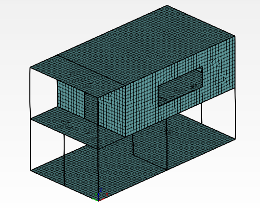
6.2. Mesh Generation Prior to Calculation#
# |
|
Step actions |
Generate a mesh from the mesh viewer tab. |
Instruction |


|
Expected results |
After a few seconds, a mesh is generated and displayed, corresponding to the structure model |
Execution |
Manual |
# |
|
Step actions |
Select a section that is assigned to one or several elements. |
Instruction |
Click on « SEC_POUTRES » from the tree view |
Expected results |
The assigned elements are highlighted in red in the Mesh Viewer. |
Execution |
Manual |

