4. Loadings and Boundary Conditions#
4.1. Global and Localized Loadings#
4.1.1. Global Load and Assign#
Creation, modification, deletion and assignment of global load.
# |
|
Step actions |
Add a load. |
Instruction |
Click on add row button in the Loads data entry table (Table View) |
Expected results |
Arow is added in the Loads table. |
Execution |
Manual |

# |
|
Step actions |
Fill in the information of the input window with invalid values. |
Instruction |

|
Expected results |
The invalid box is displayed in red and it is not possible to save the information and close the dialog |
Execution |
Manual |

# |
|
Step actions |
Fill in the information of the input window with valid values. |
Instruction |
Magnitude:9.81 m/s² Direction (X) :0.0 Direction (Y) :0.0 Direction (Z) :-1.0 |
Expected results |
The gear changes color to green. |
Execution |
Manual |
# |
|
Step actions |
Hover the mouse over the Assign box in the Loads data entry table (Table view). |
Instruction |
|
Expected results |
List the assigned elements names as atooltip. |
Execution |
Manual |
# |
|
Step actions |
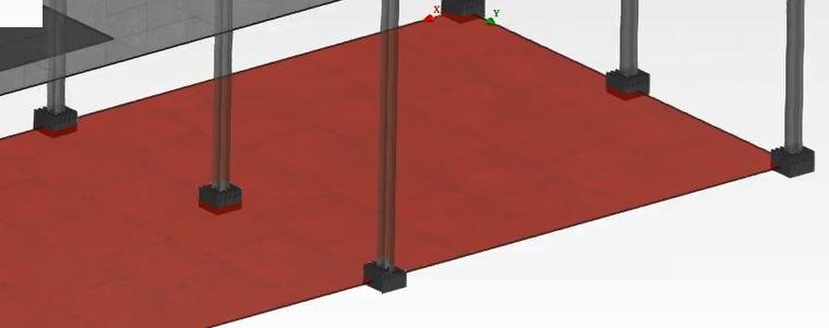
Select an element with an assignedload. |
Instruction |
Select a panel in the Model View, |
Expected results |
The selected panel is highlighted in red in red in the model viewer and its information displayed in the Informations View, revealing in particular the assigned (GRAV) load. |
Execution |
Manual |
4.1.2. Localized load#
Creation, modification, deletion, and assignment of localized load.
# |
|
Step actions |
Select a panelin the Model View. |
Instruction |
Click on a panel |
Expected results |
The panel is highlighted in red color. |
Execution |
Manual |

# |
|
Step actions |
Add loading pressure. |
Instruction |
|
Expected results |
A dialog is displayed, entitled « load definition », allowing to provide the value for the loading pressure. |
Execution |
Manual |

# |
|
Step actions |
Fill in the information of the input window with valid values. |
Instruction |
Write value: Loading pressure: -10.0 kN/m² |
Instruction |
A new row is added to the loads table, the gear is in green color (signifying a valid load) The load category is automatically set to « surfacic » and the type is « loading » |
Execution |
Manual |

# |
|
Step actions |
Hover the mouse over the Assign box in the loads date entry table (Table View). |
Instruction |
|
Expected results |
The element names to which the load applies are listed in a standard tooltip above the Assigned box. |
Execution |
Manual |
# |
|
Step actions |
Select element with an assigned load. |
Instruction |
Click on the loading pressure representation form the Model view |
Expected results |
Display in information part the loads assigned to the element selected. |
Execution |
Manual |

4.2. Boundary conditions#
Creation, modification, deletion, and assignment of boundary conditions.
Result:
If the clamp is created you must have: