2. Geometry#
2.1. Construction grid#
Creation and activation of construction supports.
# |
|
Step actions |
Add a grid. |
Instruction |
Click on the « Add Row » button in the Geometry data entry table: |
Expected results |
Add row in geometry table. |
Execution |
Manual |
# |
|
Step actions |
Delete a grid. |
Instruction |
table: 
|
Expected results |
Griddeleted. |
Execution |
Manual |
# |
|
Step actions |
Add a new grid. |
Instruction |

|
Expected results |
Arow, with the new grid, is added in the geometry table |
Execution |
Manual |
# |
|
Step actions |
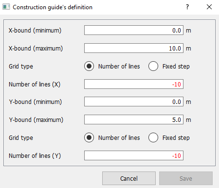
Fill in the information of the input window with invalid values. |
Instruction |

X-bound (minimum): 0.0 m X-bound (maximum): 10.0 m Grid type: Number of lines X-step: -10 Y-bound (minimum): -10 Y-bound (minimum): 0.0 m Y-bound (minimum): 0.0 m Y-bound (maximum): 0.0 m Y-bound (maximum): 5.0 m Grid type: Number of lines Y-step: a10 |
Expected results |
It is not possible to click on the Save button with invalid input. |
Execution |
Manual |
# |
|
Step actions |
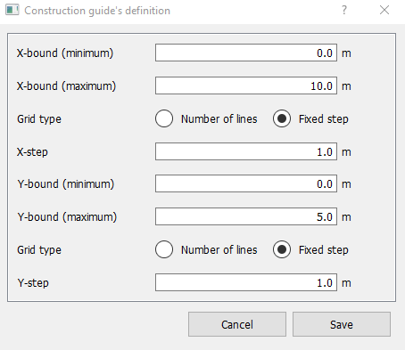
Fill in the information of the input window with valid values. |
Instruction |
Click on the button: - Input the following values: - Input the following values: X-bound (minimum): 0.0 m X-bound (minimum): 0.0 m X-bound (minimum): 1.0 Y-bound (minimum): 0.0 My-bound (maximum): 0.0 My-bound (maximum): 5.0 mGrid type: 5.0 mGrid type: Fixed step Fixed step Y-step: 1.0 - Click on save button |
Expected results |
The grid must be created with the givenvalues. |
Execution |
Manual |
# |
|
Step actions |
Display the created grid. |
Instruction |
|
Expected results |
The grid must be displayed in the model viewer. |
Execution |
Automatic |
# |
|
Step actions |
Hide the grid. |
Instruction |
Right click on the grid in the sidebar tree to select « hide » |
Expected results |
The grid must be hidden and its name no longer in bold. |
Execution |
Manual |

# |
|
Step actions |
Show the grid again. |
Instruction |
Double clicking it in the sidebar tree. |
Expected results |
The grid must be shown in the Model Viewer. |
Execution |
Manual |
2.2. Add levels#
Creation, modification, and deletion of levels.
# |
|
Step actions |
Level is selected. |
Instruction |
Double click the level it in the sidebar tree. |
Expected results |
The level’s name is shown in bold in the side bar tree. |
Execution |
Manual |
# |
|
Step actions |
Delete a level. |
Instruction |
|
Expected results |
Level is deleted. |
Execution |
Manual |
# |
|
Step actions |
Add a new level again. |
Instruction |
As in step #10 |
Expected results |
Arow, with the new level, is added in the Structure data entry table. |
Execution |
Manual |
# |
|
Step actions |
Display the created level. |
Instruction |
|
Expected results |
The level must be displayed in the model viewer. The Level’s Name Is Shown in Bold in the Side Bar Tree |
Execution |
Automatic |
2.3. Structure elements (slab, panel, column, beam)#
Slab
Creation and deletion of slab.
# |
|
Step actions |
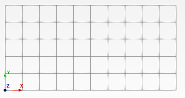
Create slab. |
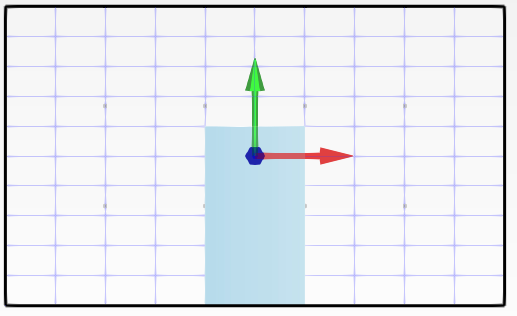
Instruction |

To see if the drawing mode is activate you must have: .. image:: images/10000000000000C200000018FB7D3921252BED43.png
(0.000, 0.000, 0.000) (0.000, 0.000) (0.000, 0.000) (0.000, 0.000) (0.000, 0.000) (0.000, 0.000, 0.000) (0.000, 0.000, 0.000) (0.000, 0.000) (0.000, 0.000, 0.000) (0.000, 0.000) (0.000, 0.000) (0.000, 0.000, 0.000) (0.000, 0.000) (0.000, 0.000, 0.000) (0.000, 0.000) (0.000, 0.000, 0.000) (0.000, 0.000) (0.000, 0.000, 0.000) (0.000, 0.000) (0.000, 0.000, 0.000) |
Expected results |
Slab is created. |
Execution |
Manual |
# |
|
Step actions |
Display slab. |
Instruction |
|
Expected results |
Slab is displayed. |
Execution |
Automatic |
# |
|
Step actions |
Delete a slab. |
Instruction |
|
Expected results |
Slab is deleted. |
Execution |
Manual |
# |
|
Step actions |
Recreate the same slab delate as step #15. |
Instruction |
As in step #15 |
Expected results |
Slab is created & displayed. |
Execution |
Manual |
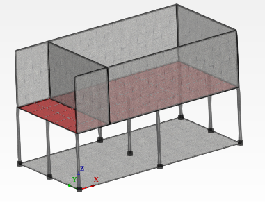
# |
|
Step actions |
Slab is selected. |
Instruction |
Click the slab’s name in the sidebar tree (under Level 0). |
Expected results |
The slab shown in red in structure. |
Execution |
Manual |
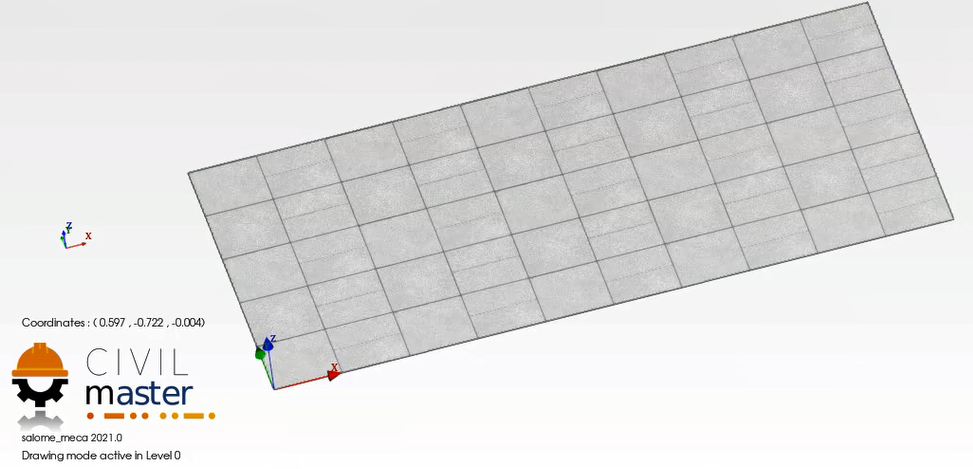
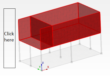
Result:
If the slab*is created* the following should show in the Model Viewer*:*
2.3.1. Column#
Creation and deletion of columns.
# |
|
Step actions |
Create several columns. |
Instruction |
In the model viewer, with the drawing mode active, double click on the following points on the grid. (0.000, 0.000 ,0.000) (0.000, 2.500, 0.000) (0.000, 5.000, 0.000) (5,000, 0.000, 0.000) (5,000, 2,500, 0.000) (5,000, 5,000, 0.000) (10,000, 0.000, 0.000) (10,000, 2,500, 0.000) (10,000, 5,000, 0.000) |
Expected results |
For each double click, a new column is created and added to the sidebar tree view. |
Execution |
Manual |
# |
|
Step actions |
Display column. |
Instruction |
|
Expected results |
The newly created columns are displayed in the model viewer. |
Execution |
Automatic |
# |
|
Step actions |
Recreate the column. |
Instruction |
Create the column as in step #20 by double clicking the given point (with the drawing mode enabled in the model viewer) (10,000, 5,000, 0.000) |
Expected results |
Column is created and displayed. |
Execution |
Manual |
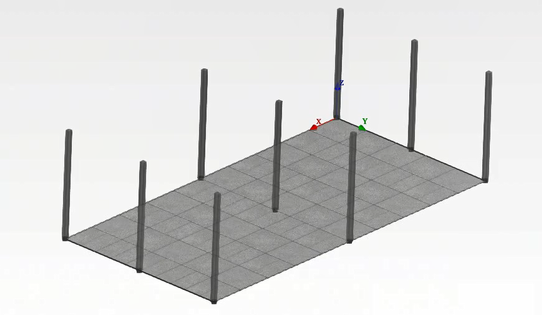
Result:
If the Columnis created the following should show in the Model Viewer:
2.3.2. Panel#
Creation, and deletion of panel.
# |
|
Step actions |
Create panel on new level 1. |
Instruction |
(0.000, 0.000, 3.000) (2.000, 0.000, 3.000) (2.000, 0.000, 3.000) (2.000, 0.000, 3.000) (2.000, 5.000, 3.000) (2.000, 5.000, 3.000) * Double click on the point on the grid (0.000, 5.000, 3.000) * Click on the point on the grid (2,000, 0.000, 3,000) * Double click on the point on the grid (2,000, 5,000, 3,000) |
Expected results |
Panelis created. |
Execution |
Manual |
# |
|
Step actions |
Panel is selected. |
Instruction |
Click the panel’s name it in the sidebar tree. |
Expected results |
The panel is highlighted in red color in the model viewer. |
Execution |
Manual |
# |
|
Step actions |
Display panel. |
Instruction |
|
Expected results |
Panel is displayed. |
Execution |
Automatic |
# |
|
Step actions |
Delete a panel. |
Instruction |
|
Expected results |
Panel is deleted. |
Execution |
Manual |
# |
|
Step actions |
Recreate the panel. |
Instruction |
As in step #24 |
Expected results |
Panel is created & displayed. |
Execution |
Manual |
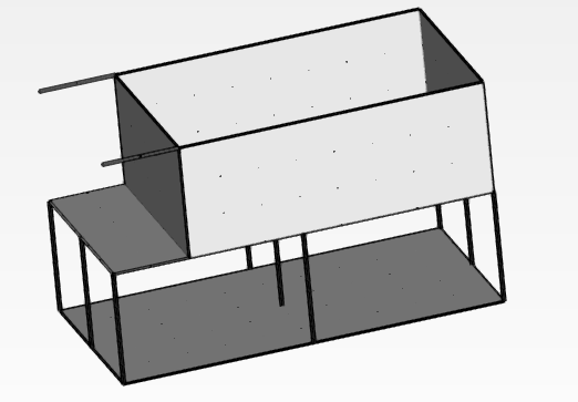
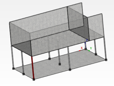
Result:
If panels/columns are created the following should show in the Model Viewer:
2.3.3. Beam#
Creation of beams by converting panels.
# |
|
Step actions |
Display beam. |
Instruction |
|
Expected results |
Beam is displayed in the model viewer. |
Execution |
Automatic |
# |
|
Step actions |
Change beam back to panel and forth to beam. |
Instruction |
|
Expected results |
Panel is created and displayed |
Execution |
Manual |
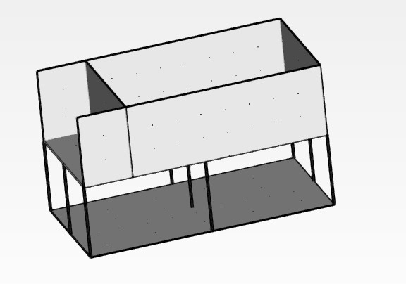
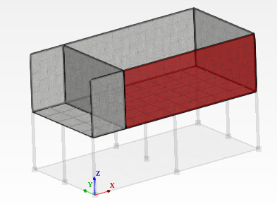
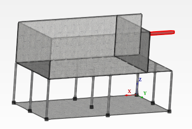
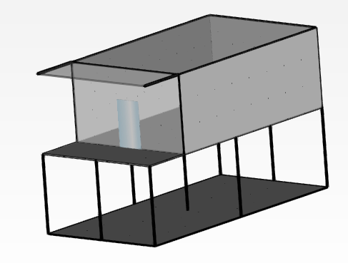
Result:
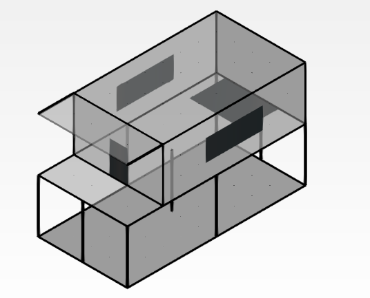
If panels/columns/beams and a last slab (as the step #15) on new level 2 (as the step #13) are created, the following should show in the Model Viewer:
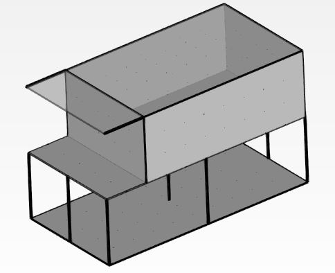
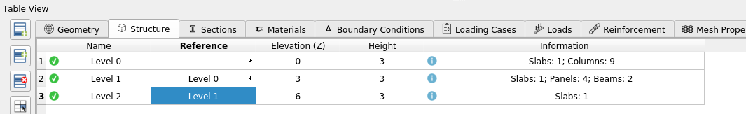
Levels are defined by:
2.4. Element selection#
Select element and highlight in the model viewer the selected element.
# |
|
Step actions |
Select a whole level from the tree view. |
Instruction |
Click on a level from the tree view. |
Expected results |
Level is highlighted in red in the model viewer with information given in the information view. |
Execution |
Manual |
# |
|
Step actions |
Unselect a level from the model viewer. |
Instruction |
Double click on an empty space next to the structure in the model viewer. |
Expected results |
Level is no longer highlighted in red and no information is displayed. |
Execution |
Manual |
# |
|
Step actions |
Select slab from the model viewer. |
Instruction |
Click on a slab from the model viewer. (in selection mode) |
Expected results |
Slab is selected and highlighted in red with information display |
Execution |
Manual |
# |
|
Step actions |
Unselect slab from the model viewer. |
Instruction |
Double click on an empty space next to the structure as in step #33 |
Expected results |
Slab is no longer selected or highlighted in red and no information is displayed. |
Execution |
Manual |
# |
|
Step actions |
Select slab from the tree view. |
Instruction |
Click on a slab from the tree view |
Expected results |
Slab is selected, highlighted in red with information display. |
Execution |
Manual |
# |
|
Step actions |
Select a panel from the model viewer. |
Instruction |
Click on a panel from the model viewer |
Expected results |
Panel is selected, highlighted in red with information display. |
Execution |
Manual |
# |
|
Step actions |
Unselect the panel from the model viewer. |
Instruction |
Double clicking on an empty space next to the structure as in step #33 |
Expected results |
Panel is no longer highlighted in red and no information is displayed. |
Execution |
Manual |
# |
|
Step actions |
Select panel from tree view. |
Instruction |
Click on a panelfrom the tree view |
Expected results |
Panel is selected, highlighted in red with information display |
Execution |
Manual |
# |
|
Step actions |
Select column from the model viewer. |
Instruction |
Click on a column from the model viewer |
Expected results |
Column is selected, highlighted in red with information display |
Execution |
Manual |
# |
|
Step actions |
Unselect a column from the model viewer. |
Instruction |
Double click on an empty space next to the structure as in step #33 |
Expected results |
Column is no longer selected or highlighted and no information is displayed. |
Execution |
Manual |
# |
|
Step actions |
Select a column from tree view. |
Instruction |
Click on a column from the tree view |
Expected results |
Column is selected, highlighted in red with information display. |
Execution |
Manual |
# |
|
Step actions |
Select beam from the model viewer. |
Instruction |
Click on a beamfrom the model viewer |
Expected results |
Beam is selected, highlighted in red with information display. |
Execution |
Manual |
# |
|
Step actions |
Unselect beam from the model viewer. |
Instruction |
Double click on an empty space next to the structure as in step #33 |
Expected results |
Beam is no longer highlighted in red color. |
Execution |
Manual |
# |
|
Step actions |
Select beam from tree view. |
Instruction |
Click on a Beamfrom the Tree View |
Expected results |
Beam selected not in red and no information display. |
Execution |
Manual |
2.5. Subzones definition (focus mode)#
Creation, modification, and deletion of subzones.
# |
|
Step actions |
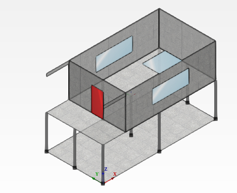
Select the panel between the beams to create a door. |
Instruction |
As in step #39 |
Expected results |
Panel is selected, highlighted in red in the model viewer and information is displayed in the specific Information View. |
Execution |
Manual |
# |
|
Step actions |
Draw zone. |
Instruction |
Click on 4 consecutive points defining a window or door. Don’t forget to click on the first point (close the loop) to create the zone |
Expected results |
Zone is created |
Execution |
Manual |
# |
|
Step actions |
Display zone. |
Instruction |
|
Expected results |
Zone is displayed |
Execution |
Automatic |
Create some surfaces to obtain this structure by following the steps 48->50
# |
|
Step actions |
Delete a zone. |
Instruction |
|
Expected results |
Isdeleted field. |
Execution |
Manual |
# |
|
Step actions |
Recreate the deleted zone. |
Instruction |
As in step #46 to #49 |
Expected results |
Zone is created again. |
Execution |
Manual |
# |
|
Step actions |
Select a zone. |
Instruction |
Click on the zone in in the Model Viewer. |
Expected results |
Zone is selected, highlighted in red with information display. |
Execution |
Manual |
# |
|
Step actions |
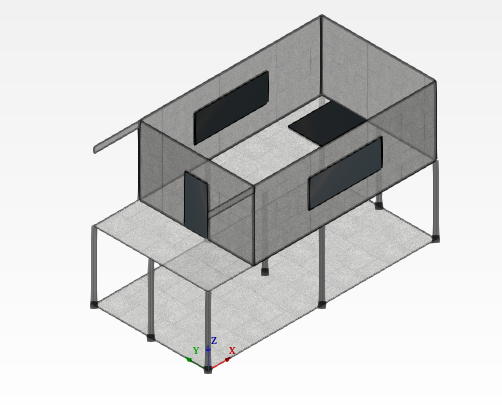
Define a zone as an opening. |
Instruction |
|
Expected results |
The zone changes color to black (opening), is identified as thus in the information display. |
Execution |
Manual |
# |
|
Step actions |
Delete an opening. |
Instruction |
|
Expected results |
Opening is deleted. |
Execution |
Manual |
# |
|
Step actions |
Recreate the zone. |
Instruction |
|
Expected results |
Zone is created and defined as an opening. |
Execution |
Manual |
# |
|
Step actions |
Change opening to a zone. |
Instruction |
|
Expected results |
Display opening selected as a zone. |
Execution |
Manual |
# |
|
Step actions |
Define the zone as an opening. |
Instruction |
As in step #54 |
Expected results |
Zone is defined as an opening. |
Execution |
Manual |
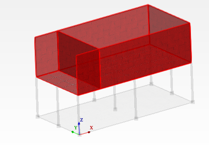
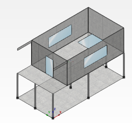
Result:
If panels/columns/beams /levels and openings are created, the following should show in the Model Viewer: