1. Reference problem#
1.1. Geometry#
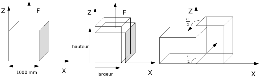
Figure 1: Reference problem (for a \(90°\) rotation)
We consider a cubic element of matter with a side of \(1000\mathrm{mm}\) subjected alternately to a tensile force and then to an overall rotation of \(45°\). It undergoes a total of 4 traction/rotation cycles.
1.2. Material data#
Here we consider the elasto-plastic behavior law with isotropic von Mises type work hardening: VMIS_ISOT_LINE. The table below lists the parameters used; in order to reinforce the comparison, the parameters used result in laws of behavior that are identical in both cases (linear isotropic work hardening).
Young’s module: |
\(200000\mathrm{MPa}\) |
Poisson’s Ratio |
\(\mathrm{0,3}\) |
Elastic limit |
\(200\mathrm{MPa}\) |
Linear work hardening module |
\(2000\mathrm{MPa}\) |
1.3. Boundary conditions and loads#
In modeling \(A\), in \(\mathrm{3D}\) we block the normal movements of the front and rear faces, in order to compare the results to the modeling \(B\) \(\mathrm{2D}\) (D_ PLAN).
In modeling \(C\), also in \(\mathrm{3D}\), the movements of the front and rear faces are left free, in order to compare the results to the modeling \(D\) \(\mathrm{2D}\) (C_ PLAN).
Two types of phases must be distinguished: traction phases and rotation phases.
First traction phase
Entity |
Load Type |
Value |
Underside |
FACE_IMPO |
|
Top side |
FACE_IMPO |
|
Rotation axis |
DDL_IMPO |
|
Front panel (\(\mathrm{3D}\)) |
FACE_IMPO |
|
Back side (\(\mathrm{3D}\)) |
FACE_IMPO |
|
Next pull-ups:
Entity |
Load Type |
Value |
Underside |
LIAISON_OBLIQUE |
|
Top side |
LIAISON_OBLIQUE |
|
Side \(X=0\); \(Z=\mathrm{1mm}\) |
|
|
Rotation axis |
DDL_IMPO |
|
Front panel (\(\mathrm{3D}\)) |
DDL_IMPO |
|
Back side (\(\mathrm{3D}\)) |
DDL_IMPO |
|
Rotation phase:
Boundary conditions
Entity |
Load Type |
Value |
Rotation axis |
DDL_IMPO |
|
Front panel (\(\mathrm{3D}\)) |
DDL_IMPO |
|
Back side (\(\mathrm{3D}\)) |
DDL_IMPO |
|
The rotation load is imposed via a macro named CHAR_ROTA; an overall rotation of \(45°\) per phase is imposed, divided into 5 increments of 9°.