7. E modeling#
7.1. Characteristics of modeling#
This is the same modeling as modeling A, but contact loading conditions are applied. The intersection is constructed with X- FEM and the level functions in the same way as for modeling A.
7.2. Characteristics of the mesh#
The mesh, identical to that of modeling A, is represented in FIG. 3.2-a. Note that the nodes of the intersected mesh are enriched 3 times, so they have the contact degrees of freedom \(\text{LAGS\_C}\), \(\text{LAG2\_C}\) and \(\text{LAG3\_C}\) in addition to the kinematic degrees of freedom.
7.3. Tested sizes and results#
The movements at the level of the crack lips are tested after having carried out the post-treatment operations relating to \(\text{X-FEM}\) (POST_MAIL_XFEM and POST_CHAM_XFEM). The DX displacement should follow function \({u}_{x}\) in equation 2.2-2. The displacement DY should follow function \({u}_{y}\) in equation 2.2-3. The deformation shown in FIG. 7.4-a is obtained.
Identification |
Reference |
0 |
|
DEPZON_1 |
DX- \({u}_{x}\) |
MIN |
|
MAX |
0 |
||
DY- \({u}_{y}\) |
MIN |
0 |
|
MAX |
0 |
||
DEPZON_2 |
DX- \({u}_{x}\) |
MIN |
0 |
MAX |
0 |
||
DY- \({u}_{y}\) |
MIN |
0 |
|
MAX |
0 |
||
DEPZON_3 |
DX- \({u}_{x}\) |
MIN |
0 |
MAX |
0 |
||
DY- \({u}_{y}\) |
MIN |
0 |
|
MAX |
0 |
||
DEPZON_4 |
DX- \({u}_{x}\) |
MIN |
0 |
MAX |
0 |
||
DY- \({u}_{y}\) |
MIN |
0 |
|
MAX |
0 |
||
Table 7.3-1
The deformation is represented in FIG. 7.4-a. The color code represents the movement field.
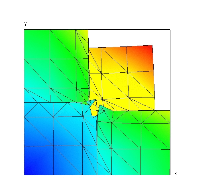
Figure 7.4-a: Deformed structure (Exaggeration 10).
We test the value of \({E}^{e}\) produced by the POST_ERREUR operator (expressed in \(\text{J}\times {\text{m}}^{-1}\)).
Identification |
Reference type |
Reference value |
Ee |
“ANALYTIQUE” |
1.3975 106 |
We test the value of \({\Vert u\Vert }_{{L}^{2}}\) produced by the POST_ERREUR operator.
7.4. notes#
A high error is obtained. Indeed, the implementation of the redistribution of contact facets has not been implemented. Contact forces on these facets are not taken into account in the calculation. The affected zone concerns in particular the point of intersection of the cracks (which are not tested) as well as the element containing it. Note that the results are significantly improved when the mesh is refined.