3. Modeling A#
3.1. Characteristics of modeling#
This is an X- FEM modeling, in plane deformations. Interfaces are defined by level functions (normal level sets noted \(\text{LN}\)).
The equations of the level functions for the horizontal and vertical interfaces are as follows:
\(\text{LN}1=Y\) eq 3.1-1
\(\text{LN}2=X\) eq 3.1-2
The horizontal interface is defined in the classical way using the DEFI_FISS_XFEM operator with the normal \(\text{LN1}\) level set.
To define the vertical interface, we proceed in two steps. For the first time, we call the operator DEFI_FISS_XFEM with the normal level set \(\text{LN2}\), by defining a point « above » the horizontal crack for the keyword JONCTION (the point is not necessarily on the level set). This step makes it possible to define the upper part of the vertical interface (see figure 3.1-a in the center). The operator DEFI_FISS_XFEM is called a second time in the same way, but by defining a point « below » the crack (see Figure 3.1-a on the right).
We therefore called DEFI_FISS_XFEM a total of 3 times (creation of 3 crack objects) to define the two interfaces that intersect. From a theoretical point of view, each crack object adds a Heaviside enrichment. This makes a total of three Heaviside degrees of freedom in addition to the classical degrees of freedom. We therefore have 4 degrees of freedom at the intersection, which makes it possible to move independently the 4 zones generated by the 2 interfaces.
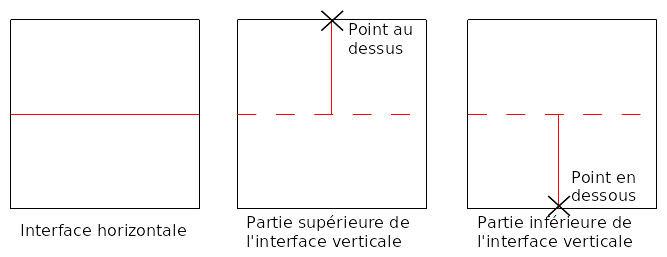
Figure 3.1-a: Intersection construction steps.
3.2. Characteristics of the mesh#
The mesh, which comprises 25 cells of the QUAD4 type, is represented in FIG. 3.2-a.
It can be seen in this figure that the central mesh is cut by the two interfaces. This test therefore makes it possible to validate multiple division. Note that the knots in this mesh are enriched 3 times, so they have the degrees of freedom \(\mathit{DX}\), \(\mathit{DY}\), \(\mathit{H1X}\), \(\mathit{H1Y}\), \(\mathit{H2X}\), \(\mathit{H2Y}\), \(\mathit{H3X}\) and \(\mathit{H3Y}\).
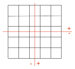
Figure 3.2-a: The modeling mesh A.
3.3. Tested sizes and results#
The movements at the level of the crack lips are tested after having carried out the post-treatment operations relating to \(\text{X-FEM}\) (POST_MAIL_XFEM and POST_CHAM_XFEM). The displacement \(\mathit{DX}\) must correspond to the load imposed in Figure 1.3-a on each of the zones and \(\mathit{DY}\) must be zero. We test the min and the max on the lips of each of the zones.
Identification |
Reference |
Reference type |
Precision |
10^ -12% |
|
DEPZON_1 |
DX |
MIN |
-0.25 |
“ANALYTIQUE” |
|
MAX |
-0.25 |
“ANALYTIQUE” |
10^ -12% |
||
DY |
MIN |
0 |
“ANALYTIQUE” |
10^ -12% |
|
MAX |
0 |
“ANALYTIQUE” |
10^ -12% |
||
DEPZON_2 |
DX |
MIN |
-0.5 |
“ANALYTIQUE” |
10^ -12% |
MAX |
-0.5 |
“ANALYTIQUE” |
10^ -12% |
||
DY |
MIN |
0 |
“ANALYTIQUE” |
10^ -12% |
|
MAX |
0 |
“ANALYTIQUE” |
10^ -12% |
||
DEPZON_3 |
DX |
MIN |
0.75 |
“ANALYTIQUE” |
10^ -12% |
MAX |
0.75 |
“ANALYTIQUE” |
10^ -12% |
||
DY |
MIN |
0 |
“ANALYTIQUE” |
10^ -12% |
|
MAX |
0 |
“ANALYTIQUE” |
10^ -12% |
||
DEPZON_4 |
DX |
MIN |
0.75 |
“ANALYTIQUE” |
10^ -12% |
MAX |
0.75 |
“ANALYTIQUE” |
10^ -12% |
||
DY |
MIN |
0 |
“ANALYTIQUE” |
10^ -12% |
|
MAX |
0 |
“ANALYTIQUE” |
10^ -12% |
||
Table 3.3-1
The deformation is represented in FIG. 3.4-a. The color code represents the movement field.
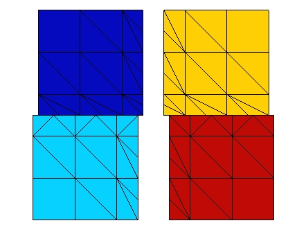
Figure 3.4-a: Deformed structure.
We test the value of \({E}^{e}\) produced by the POST_ERREUR operator.
Identification |
Reference type |
Reference value |
Ee |
“ANALYTIQUE” |
0 |
We test the value of \({\parallel u\parallel }_{{L}^{2}}\) produced by the POST_ERREUR operator.