3. Modeling A#
3.1. Characteristics of modeling#
We use a AXIS model (linear elements).

The discrete contact formulation is used (active stress method).
3.2. Characteristics of the mesh#
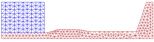
Number of knots: 333
Number of meshes: 510 TRIA3 and 152 SEG2
Number of nodes in contact: 20
3.3. Tested sizes and results#
The following displacement \(Y\) of the point \(K\) of the piece of paper with respect to the surface \(\mathrm{ABCDEFG}\) of the die is tested.
Identification |
Reference type |
Reference value |
Tolerance |
Point \(K\)/Point \(B\) - \(\mathrm{DY}\) |
“ANALYTIQUE” |
5.0000 |
|
Point \(K\)/Point \(C\) - \(\mathrm{DY}\) |
“ANALYTIQUE” |
20.8250 |
|
Point \(K\)/Point \(D\) - \(\mathrm{DY}\) |
“ANALYTIQUE” |
55.8800 |
|
Point \(K\)/Point \(E\) - \(\mathrm{DY}\) |
“ANALYTIQUE” |
78.6900 |
|
Point \(K\)/Point \(F\) - \(\mathrm{DY}\) |
“ANALYTIQUE” |
144.8950 |
|
Point \(K\)/Point \(G\) - \(\mathrm{DY}\) |
“ANALYTIQUE” |
155.0960 |
|
Checking mode RESOLUTION =” NON “:
Identification |
Reference type |
Reference value |
Tolerance |
Point \(K\)/Point \(G\) - \(\mathrm{DY}\) |
“ANALYTIQUE” |
155.0960 |
|
Game \(\mathrm{LC}\) |
“ANALYTIQUE” |
-5.0000 |
|
Game \(LE\) |
“ANALYTIQUE” |
-2.0000 |
|
3.4. notes#
The calculation is carried out by imposing a displacement on the back side of the block \(\text{(MN)}\). The displacement is imposed as follows:
|
0.mm to |
5.mm in 5 steps |
|
5.mm to |
20.mm in 5 steps |
|
20.mm to |
50.mm in 5 steps |
|
50.mm to |
70.mm in 5 steps |
|
70.mm to |
140.mm in 5 steps |
|
140.mm to |
155.mm in 5 steps |
The calculations do not converge with the default keywords used for convergence in STAT_NON_LINE, because the default value of RESI_GLOB_RELA = 1.E-6 is too restrictive (the forces to which the piece is subjected are initially relatively weak). To overcome this problem, use the keyword RESI_GLOB_MAXI = 1.E-6.