1. Reference problem#
1.1. Geometry#
We consider a square plate with side \(20m\) in plane deformations, centered in the \((X,Y)\) coordinate system. The cracks are defined by the points \(A\) to \(J\) and \(A\text{'}\) to \(J\text{'}\), whose coordinates are given in table 1. The cracks are shown in FIG. 1.
Points |
\(X\) |
\(Y\) |
Points |
\(X\) |
\(Y\) |
|
\(A\) |
−3.0851 |
0.75 |
\(A\text{'}\) |
3,08512 |
−0.75 |
|
\(B\) |
0.50000 |
1,13327 |
\(B\text{'}\) |
−0.5000 |
−0.3667 |
|
\(C\) |
0.20309 |
1,55730 |
\(C\text{'}\) |
−0.2031 |
0.05730 |
|
\(D\) |
−2,1454 |
1.09202 |
\(D\text{'}\) |
2,14543 |
−0.4080 |
|
\(E\) |
−1.3794 |
0.44923 |
\(E\text{'}\) |
1,37939 |
−1.0508 |
|
\(F\) |
−3.0851 |
−0.25 |
\(F\text{'}\) |
3,08512 |
−1.75 |
|
\(G\) |
−2.3780 |
0.45711 |
\(G\text{'}\) |
2,37802 |
−1.0429 |
|
\(H\) |
−1.3794 |
1.09202 |
\(H\text{'}\) |
1,37939 |
−0.4080 |
|
\(I\) |
−0.5134 |
1,59202 |
\(I\text{'}\) |
0.51336 |
0.09202 |
|
\(J\) |
−0.4397 |
0.79125 |
\(J\text{'}\) |
0.43969 |
−0.7087 |
Table 1: coordinates of the points defining the cracks.
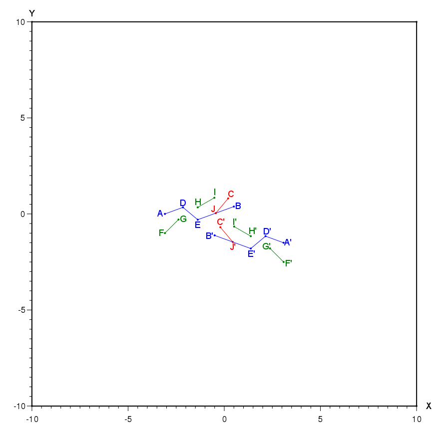
Figure 1: position of points and cracks.
1.2. Material properties#
The material is isotropic elastic with the following properties:
\(E\mathrm{=}\mathrm{0,1}\mathit{MPa}\)
\(\nu =0.3\)
1.3. Boundary conditions and loads#
Constraint \(\sigma \mathrm{=}(\begin{array}{cc}1& 1\\ 1& 1\end{array})\) is imposed on the entire outline of the structure. This corresponds to a loading in bi-traction and unit shear. Rigid fashions are blocked.
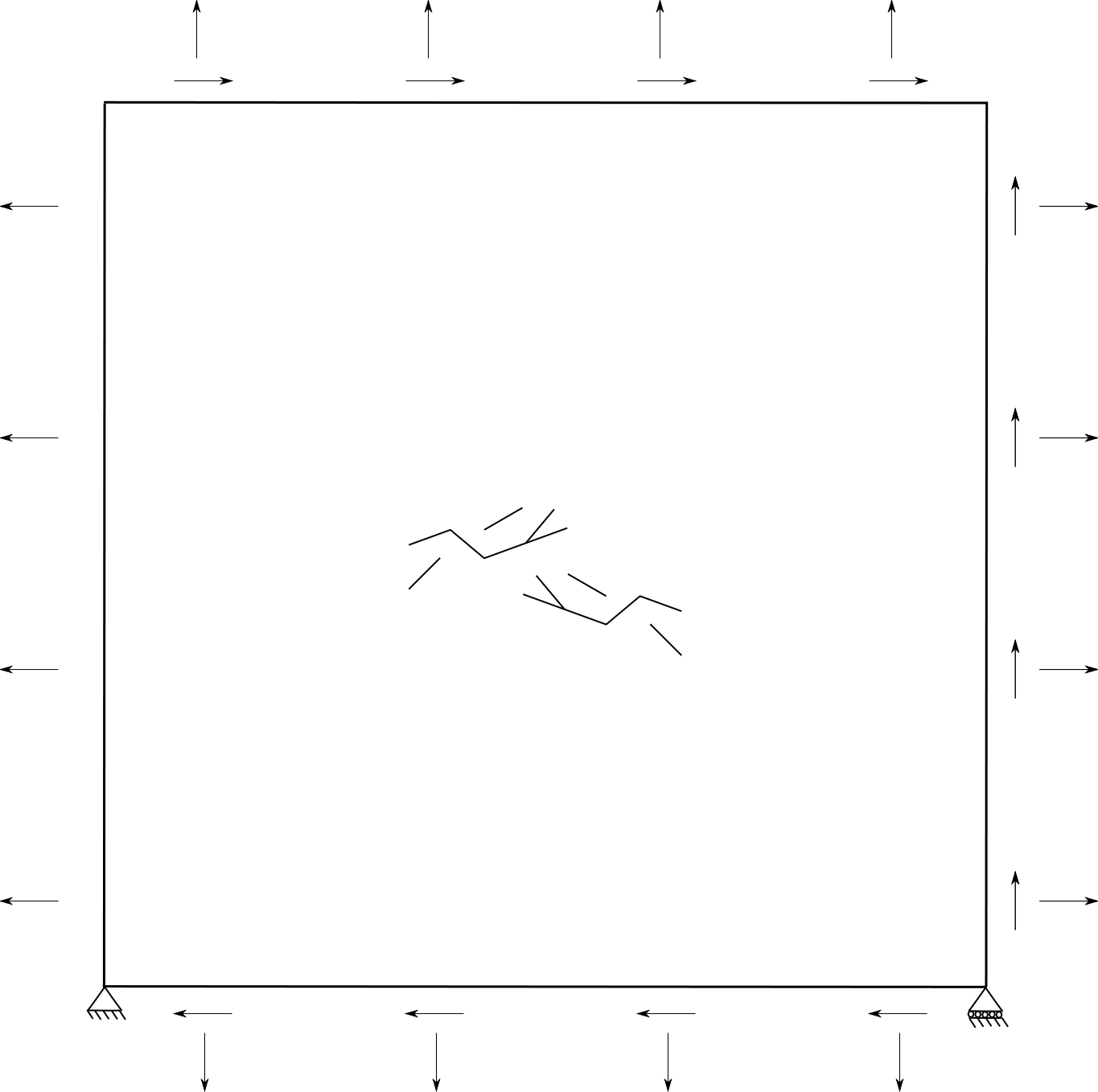
Figure 2: loading the structure.