8. F modeling#
8.1. Characteristics of modeling#
It is a 3D model. The master and slave surfaces facing each other are such that their mesh is not compatible. To avoid having calculations that are too slow, we will only take a quarter of the geometry.
Young’s modulus \({E}_{1}\mathrm{=}{E}_{2}\) and Poisson’s coefficients \({\nu }_{1}\mathrm{=}{\nu }_{2}\) are \(1.0E9\mathit{Pa}\) and \(0.2\) respectively. The pressure applied to the edge of the outer ring is \(1.0E7+\mathrm{10E5.cos}(2\theta )(\mathit{Pa})\), \(\theta\) being the polar angle.
The pressure does not vary in the longitudinal direction. To have a model in accordance with the plane deformations, zero longitudinal displacement will be imposed on the two upper surfaces (in red in FIG. 8.2-1). Solution displacements will be applied as boundary conditions on the other surfaces (in blue in figure 8.2-1).
The outer ring defines the master surface.
8.2. Characteristics of the mesh#
The mesh (Figure 8.2-1) includes:
464 QUAD4 meshes;
400 HEXA8 meshes.
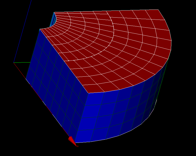
Figure 8.2-a : The F modeling mesh**
8.3. Tested sizes and results#
Note \(\lambda\) the contact pressure calculated analytically, \(({U}_{x},{U}_{y},{U}_{z})\) the displacements calculated analytically.
In the case where the displacements are zero, an absolute limit is defined equal to 2% the value of the maximum displacement Vmax=5.5E-03.
The contact pressure (LAGS_C) and the displacement components (DX, DY, DZ) are calculated for the nodes below:
N125 (0.421224E-01, 4.427282E-01, 0.00000000000000E+00)
N285 (0.421224E-01, 4.427282E-01, 4.00000000000000E-01)
N790 (0.421224E-01, 4.427282E-01, 2.00000000000000E-01)
Identification |
Reference |
Aster |
tolerance |
LAGS_C at node 125 |
|
Analytics |
2.10-2 |
DX at node 125 |
|
Analytics |
2.10-2 |
DY at node 125 |
|
Analytics |
2.10-2 |
DZ to node 125 |
|
Analytics |
1.E-8 |
LAGS_C at node 285 |
|
Analytics |
2.10-2 |
DX at node 285 |
|
Analytics |
2.10-2 |
DY at node 285 |
|
Analytics |
2.10-2 |
DZ at node 285 |
|
Analytics |
1.E-8 |
LAGS_C at node 790 |
|
Analytics |
2.10-2 |
DX at node 790 |
|
Analytics |
2.10-2 |
DY at node 790 |
|
Analytics |
2.10-2 |
DZ at node 790 |
|
Analytics |
1.E-8 |
Table 8.3-1
8.4. Comments#
The results relating to this model should be considered carefully: the need to create an incompatible mesh for the master and slave contact surfaces, representing only a quarter of the geometry, and which does not generate positive pressure at the edges, makes it necessary to geometrically confuse the nodes at the edges of the meshes of the master and slave contact surfaces. This generates a relatively incorrect and oscillating pressure profile at the edges of the contact surface. This effect decreases by refining the mesh.