1. Reference problem#
1.1. Geometry and loading#
Consider a square plate with side \(2000\mathit{mm}\) with a hole of radius \(R\mathrm{=}500\mathit{mm}\) centered in the vertical direction and offset in the horizontal direction (see Figure 1.1-a). The plate has a horizontal plane of symmetry (\(\mathit{AB}\text{'}\)) passing through the center of the hole. This symmetry can allow us to reduce our study to the upper half of the plate when possible.
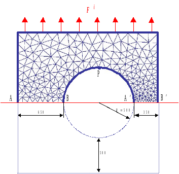

Figure1.1-a: Diagram of the perforated plate, boundary conditions, and loading.
It is considered a priori that the cracks will develop along the axis of symmetry on both sides of the hole. The cohesive elements are therefore arranged along the paths \([\mathrm{AB}]\) and \([A\text{'}B\text{'}]\). The loading consists of applying a unit surface force density \({F}^{i}\) directed in the \(Y\) direction on the upper part of the domain. The intensity of this force will be given by controlling the load (see [R7.02.11]). Moreover, symmetry conditions (zero displacements following \(Y\)) are imposed on the lower face of the cohesive elements. Finally, rigid body movements are blocked by imposing a zero displacement following \(X\) on point \(P\), the top of the hole.
For E to J models, we have an X- FEM formulation: it is then necessary to model the entire structure for the moment. An interface is introduced on the \((AB\text{'})\) right. We recall the approximation of the field of movement for the nodes whose support is intersected by an interface XFEM:
\({u}_{h}(x)\mathrm{=}\mathrm{\sum }_{i}{\phi }_{i}(x){a}_{i}+\mathrm{\sum }_{i}{\phi }_{i}(x){b}_{i}H(\mathit{lsn}(x))\)
In order to block rigid body movements, we want the interface to be an axis of symmetry for the problem. If we consider \({M}^{\text{+}}\) and \({M}^{\text{-}}\) to be the points immediately above and below the interface, we want \({u}_{y}({M}^{\text{+}})+{u}_{y}({M}^{\text{-}})\mathrm{=}0\).
For a compliant interface, this implies \({a}_{y}\mathrm{=}0\) on the interface nodes (figure).
For a non-compliant interface that intersects the edges in their middle, noting \({N}_{\text{SUP}}\) and \({N}_{\mathit{INF}}\) as the nodes opposite each other on either side of the crack (figure), this implies:
\({a}_{y}({N}_{\text{SUP}})+{a}_{y}({N}_{\text{INF}})\mathrm{=}0\)
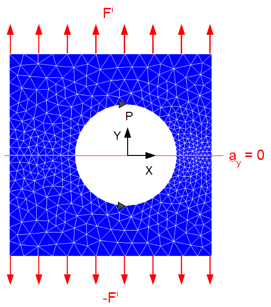
Figure 1.1-a : load with a conformal crack.
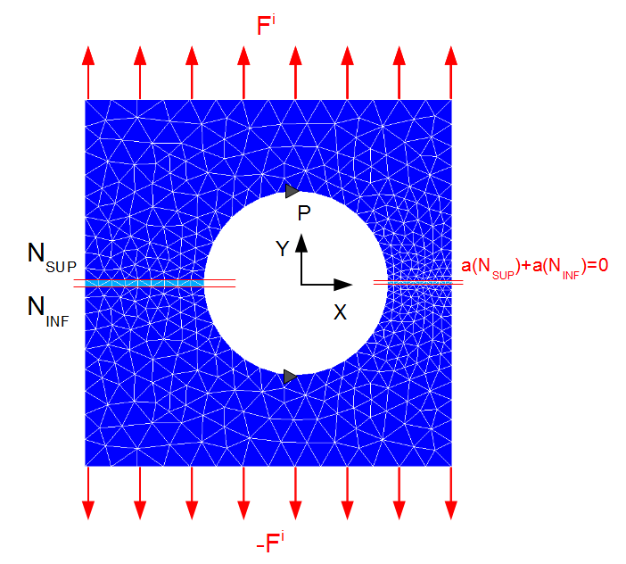
Figure 1.1-b : load for a non-compliant crack.
1.2. Material properties#
The values of the Young’s modulus, the Poisson’s ratio, the critical stress and the toughness of the material are chosen in the following way:
\(\begin{array}{ccc}E\mathrm{=}30000\mathit{MPa}& \nu \mathrm{=}0.2& {\sigma }_{c}\mathrm{=}0.2\mathit{MPa}\\ {G}_{c}\mathrm{=}100\mathit{Pa.mm}& \text{}\mathrm{\Rightarrow }\text{}& \text{problème symétrisé}\\ {G}_{c}\mathrm{=}200\mathit{Pa.mm}& \text{}\mathrm{\Rightarrow }\text{}& \text{problème non symétrisé}\end{array}\)
These are « test » values that do not correspond to any particular material. The aim of the choice of cohesive parameters is to obtain a solution with a relatively coarse mesh size. It should be noted that to ensure a correct solution (precision and good convergence) with these models, it is necessary that there are several elements in the cohesive zone (see doc [U2.05.07]).
Note:
When the mechanical problem is symmetrized, only half of the cracks (one lip) are modelled. The latter dissipate half as much energy as if the entire plate had been modelled. To model a material with a given toughness
, it is therefore necessary to perform the simulation with a value of
.