6. E modeling#
6.1. Characteristics of modeling E#
An equation \(\left[Y\mathrm{=}0\right]\) interface is introduced into the model using a XFEM formulation, via a normal level set. The simulation of the propagation of cracks by brittle fracture is carried out thanks to a CZM_EXP_REG relationship between stress and displacement jump between the lips of the interface. Syntactically, this relationship is included in the definition of a contact zone between the two lips of the crack, with integration FPG3 or FPG2 and in formulation CZM. This means that the contact is managed by the cohesive law and that there is no friction. Physically, we then find ourselves rigorously in the same situation as modeling \(D\). The solid elements, in plane deformations D_ PLAN, are elastic.
6.2. Characteristics of the mesh#
The perforated plate is meshed in accordance with the crack.
Volume elements (\(\mathrm{DCB}\)): 804 TRI3
6.3. Tested sizes and results#
Modeling \(D\) is used as a reference. It can be seen from the figure that the results are perfectly comparable.
Size tested |
Reference Type |
Code_Aster |
Tolerance ( \(\text{\%}\) )) ** |
\(U\) at time 50 |
|
3.32215D-03 |
0.10 |
\(F\) at time 50 |
|
4.21054D+07 |
0.10 |
\(U\) at time 100 |
|
2.52359D-03 |
0.10 |
\(F\) at time 100 |
|
5.3546D+06 |
0.10 |
\(U\) at the moment 150 |
|
7.09118D-03 |
0.10 |
\(F\) at the moment 150 |
|
6.75039D+06 |
0.10 |
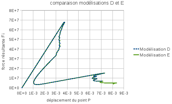
Figure 6.3-a : adequacy of modeling D with modeling E
6.4. Comments#
Solutions \(\mathit{FEM}\) can be superimposed on solutions \(\mathrm{XFEM}\) which have the same cohesive law. Therefore, this test makes it possible to validate the \(\mathrm{XFEM}\) implementation of the cohesive law, as well as that of piloting by elastic prediction.