6. D modeling#
6.1. Characteristics of modeling#
Modeling POU_D_TGM (SEG2)
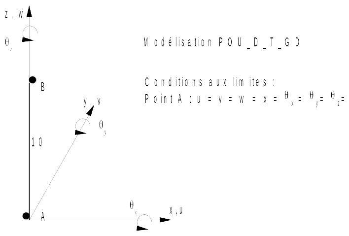
6.2. Characteristics of the mesh#
Number of knots: 11
Number of meshes and type: 10 SEG2 evenly distributed in length
6.3. Characteristics of the cross-section mesh (fibers)#
Number of fibers: 50 (5 in the width and 10 in the thickness)
Number of meshes and type: 50 QUA4
6.4. Tested sizes and results#
6.4.1. Tested values#
The calculation strategy used is divided into two steps:
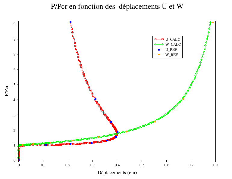
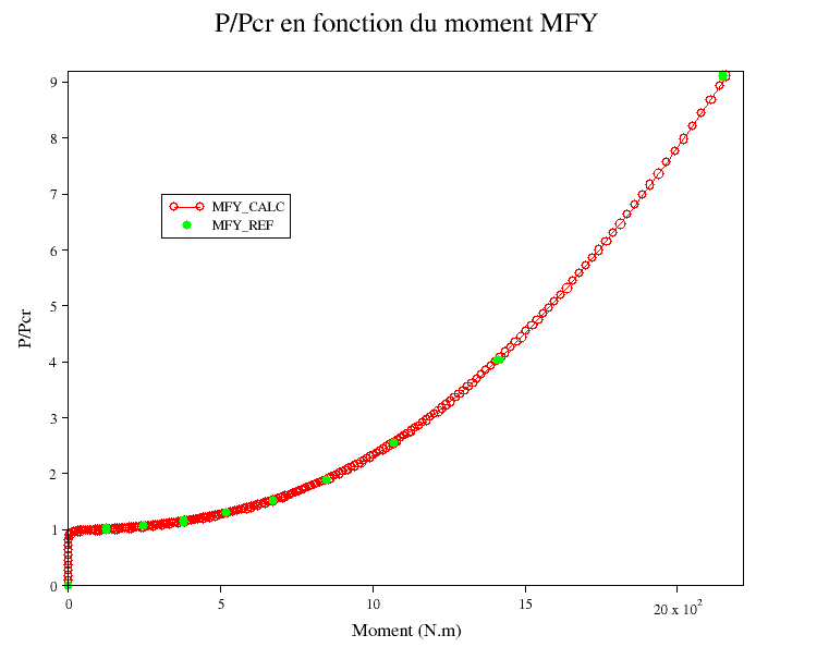
Imposed load: The structure was pre-deformed according to its first buckling mode and with a very low amplitude compared to the length of the beam (in the order of \({5.10}^{\mathrm{-}4}m\)). Charging is applied up to \(P\mathrm{/}{P}_{\mathit{cr}}\mathrm{=}0.95\).
Imposed displacement: clear of 0.95, the structure begins to undergo a strong lateral displacement for a very small increase in load, so the structure is controlled in arc length to determine the post-buckling behavior.
The results are in good agreement with the reference solution starting from ETA_PILOTAGE = 1.152. Before this value, pre-deformation (necessary to obtain buckling) degrades the solution, and the differences with analytical solutions are significant (up to 60%). The corresponding values are subject to non-regression tests. But this difference is only linked to the initial (arbitrary) pre-deformation, since by increasing the vertical loading, we find the right solution.
DZ |
Identification |
Instants |
Reference |
—0.22 |
X |
3.8 |
0.3595 |
DZ |
3.8 |
—0.22 |
|
ETA_PILOTAGE |
3.8 |
1.293 |
|
MYY |
3.8 |
519.41 |
|
—0.3255 |
XX |
4.56 |
0.396 |
DZ |
4.56 |
—0.3255 |
|
ETA_PILOTAGE |
4.56 |
1.518 |
|
MYY |
4.56 |
674.3 |
|
—0.4385 |
XX |
5.358 |
0.4015 |
DZ |
5.358 |
—0.4385 |
|
ETA_PILOTAGE |
5.358 |
1.884 |
|
MYY |
5.358 |
849.74 |