5. C modeling#
5.1. Characteristics of modeling#
5.2. Characteristics of the mesh#
Number of knots: 11
Number of meshes and type: 10 SEG2
5.3. Tested sizes and results#
5.3.1. Tested values#
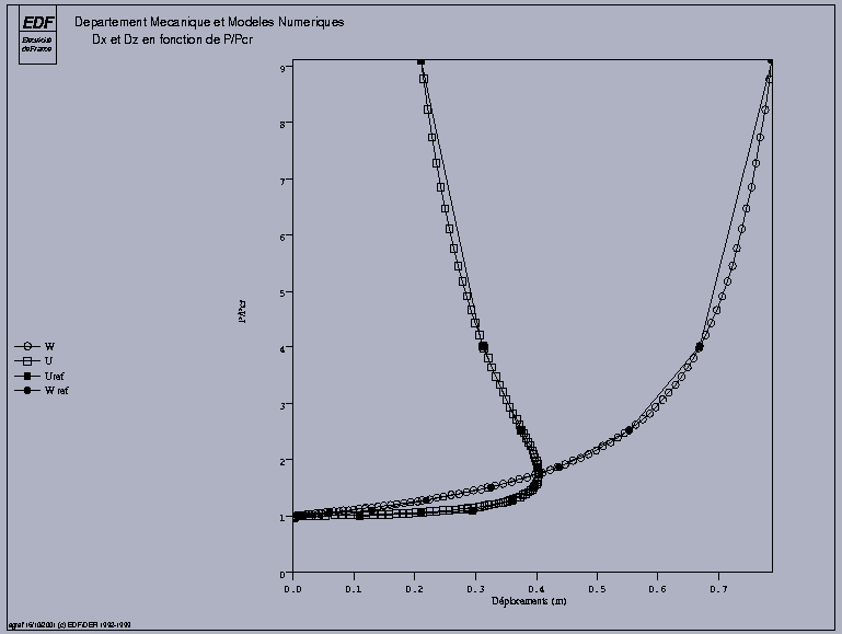
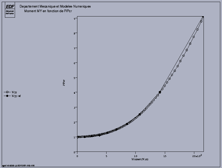
The calculation strategy used is divided into two steps:
Imposed load: a disruptive load of \(1\mathrm{/}1000\) of the critical load following \(X\) is imposed to reveal the buckling mode. This load is applied for \(P\mathrm{/}{P}_{\mathit{cr}}\mathrm{=}0.98\) and up to \(P\mathrm{/}{P}_{\mathit{cr}}\mathrm{=}1.015\).
Imposed displacement: clear of 1.01, the structure has become very flexible, an increase in displacement DZ is imposed (option DDL_IMPO in STAT_NON_LINE) to determine the post-buckling behavior.
The results are in good agreement with the reference solution starting at ETA_PILOTAGE = 1.293. Before this value, the disturbing load (necessary to obtain buckling) degrades the solution, and the differences with the analytical solutions are significant (up to 80%). The corresponding values are subject to non-regression tests. But this difference is only linked to the disturbing load, since by increasing the vertical loading, we find the right solution.
DZ |
Identification |
Instants |
Reference |
—0.22 |
XX |
1.18684 |
0.3595 |
DZ |
1.18684 |
—0.22 |
|
ETA_PILOTAGE |
1.18684 |
1.293 |
|
MYY |
1.18684 |
519.41 |
|
—0.3255 |
XX |
1.24521 |
0.396 |
DZ |
1.24521 |
—0.3255 |
|
ETA_PILOTAGE |
1.24521 |
1.518 |
|
MYY |
1.24521 |
674.3 |
|
—0.4385 |
XX |
1.30521 |
0.4015 |
DZ |
1.30521 |
—0.4385 |
|
ETA_PILOTAGE |
1.30521 |
1.884 |
|
MYY |
1.30521 |
849.74 |
In addition, we test the value of the support reactions at the initial moment in order to validate the consideration of TYPE_CHARGE =” FIXE_PILO “in CALC_CHAMP/EXCIT when reuse is absent.
Identification |
Reference value |
Reference type |
Tolerance |
Field REAC_NODA, NodeN1, DZ Component |
“ANALYTIQUE” |
1E-3 |