4. B modeling#
4.1. Characteristics of modeling#
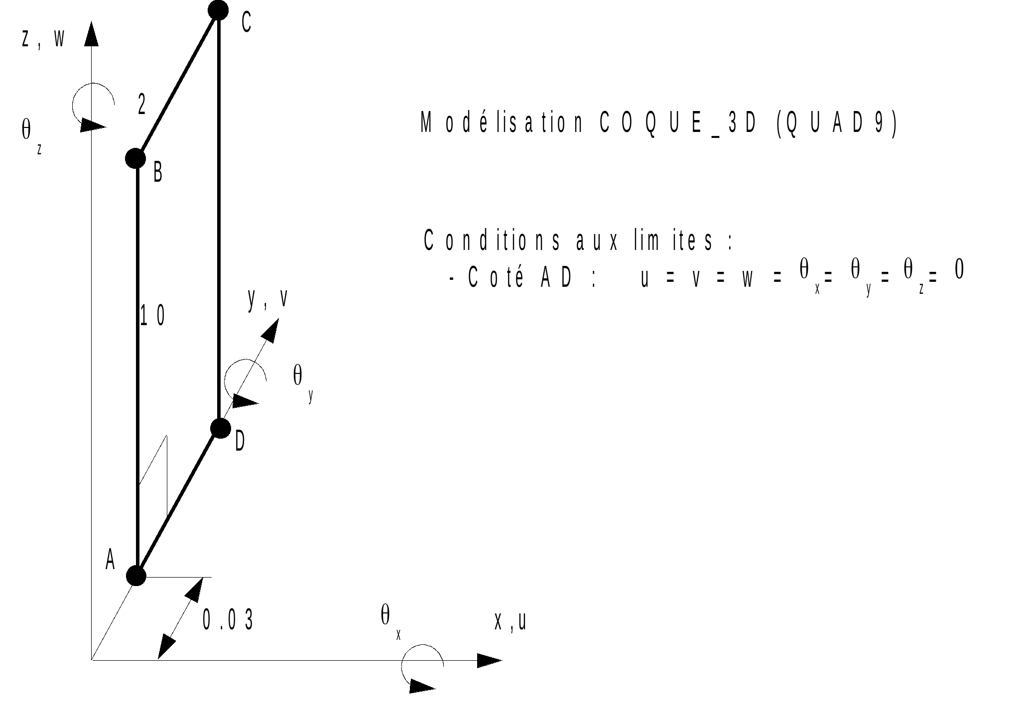
4.2. Characteristics of the mesh#
Number of knots: 105
Number of meshes and type: 20 QUAD9
4.3. Tested sizes and results#
The calculation strategy used is divided into two steps:
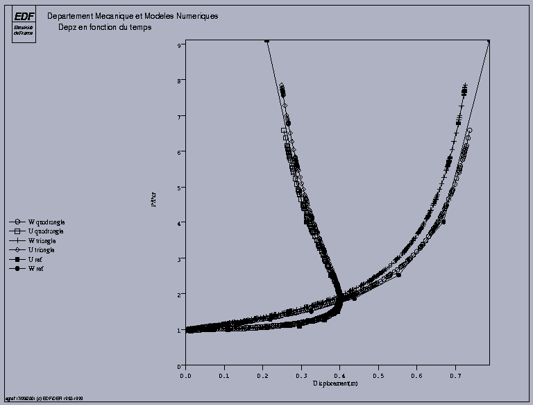
Imposed load: a disruptive load of \(1/1000\) of the critical load following \(X\) is imposed to reveal the buckling mode. This load is applied for \(P/{P}_{\mathit{cr}}=0.98\) and up to \(P/{P}_{\mathit{cr}}=1.015\).
Imposed displacement: clear of 1.01, the structure has become very flexible, an increase in displacement DZ is imposed (option DDL_IMPO in STAT_NON_LINE) to determine the post-buckling behavior.
Using the arc-length technique makes it difficult to define the reference value to be entered in the TEST_RESU command, since these values cannot be imposed. To define the reference values, we looked for the values of DZ that were as close as possible to those listed in the table in [§2.2] and we reported the values of the control parameter and of DX that we had to obtain for the values of DZ in question.
DZ |
Identification |
Instants |
Reference |
|
—0.0150 |
X |
1.0356 |
0.110 |
|
DZ |
1.03356 |
—0.0150 |
||
ETA_PILOTAGE |
1.03356 |
1.015 |
||
—0.0595 |
X |
1.08921 |
0.2110 |
|
DZ |
1.08921 |
—0.0595 |
||
ETA_PILOTAGE |
1.08921 |
1.063 |
||
—0.22 |
XX |
1.20259 |
0.3595 |
|
DZ |
1.20259 |
—0.22 |
||
ETA_PILOTAGE |
1.20259 |
1.293 |
||
—0.3255 |
XX |
1.2521 |
0.396 |
|
DZ |
1.25521 |
—0.3255 |
||
ETA_PILOTAGE |
1.2521 |
1.2521 |
1.518 |
|
—0.5535 |
X |
1.37521 |
0.375 |
|
DZ |
1.37521 |
—0.5535 |
||
ETA_PILOTAGE |
1.37521 |
2.541 |
||
—0.67 |
XX |
1.45321 |
0.3125 |
|
DZ |
1.45321 |
—0.67 |
||
ETA_PILOTAGE |
1.45321 |
4.029 |