3. Modeling A#
3.1. Characteristics of modeling#
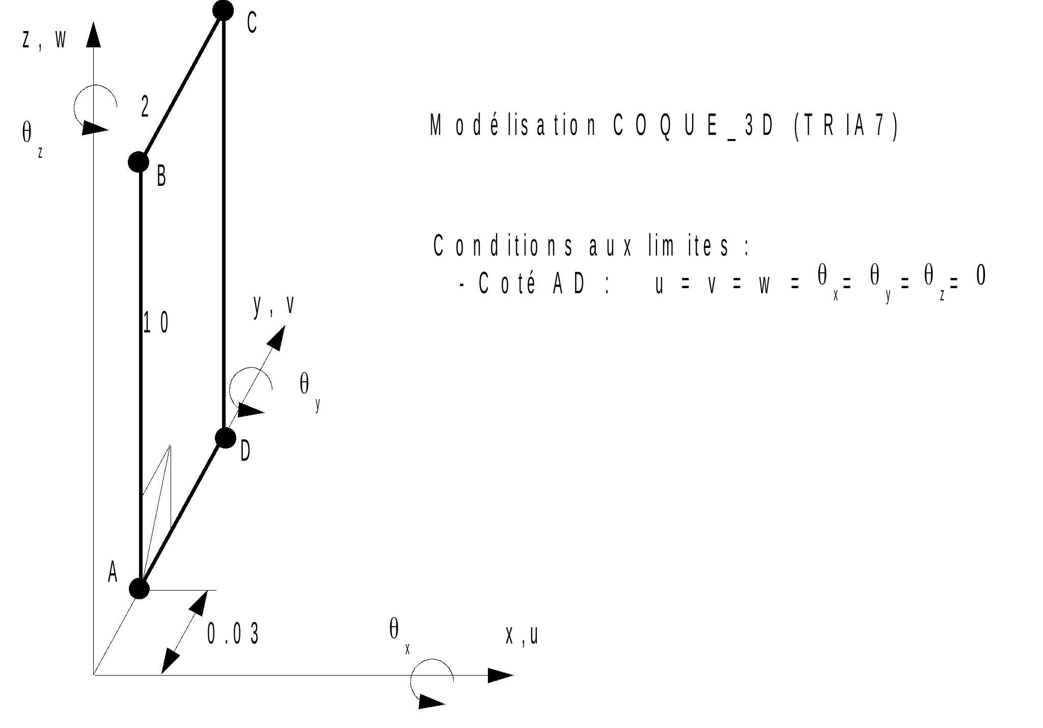
Modeling COQUE_3D (TRIA7)
3.2. Characteristics of the mesh#
Number of knots: 145
Number of meshes and type: 40 TRIA7
3.3. Tested sizes and results#
The calculation strategy used is divided into two steps:
Imposed load: a disruptive load of \(1\mathrm{/}1000\) of the critical load following \(X\) is imposed to reveal the buckling mode. This load is applied for \(P\mathrm{/}{P}_{\mathit{cr}}\mathrm{=}0.98\) and up to \(P\mathrm{/}{P}_{\mathit{cr}}\mathrm{=}1.015\).
Imposed displacement: clear of 1.01, the structure has become very flexible, an increase in displacement DZ is imposed (option DDL_IMPO in STAT_NON_LINE) to determine post-buckling behavior.
Using the arc-length technique makes it difficult to define the reference value to be entered in the TEST_RESU command, since these values cannot be imposed. To define the reference values, we looked for the DZ values that were as close as possible to those listed in the [§2.2] table and we reported the values of the control parameter and DX that we had to obtain for the DZ values in question.
DZ |
Identification |
Instants |
Reference |
—0.0150 |
XX |
1.04532 |
0.1100 |
DZ |
1.04532 |
—0.0150 |
|
ETA_PILOTAGE |
1.04532 |
1.015 |
|
—0.0595 |
X |
1.09788 |
0.2110 |
DZ |
1.09778 |
—0.0595 |
|
ETA_PILOTAGE |
1.09778 |
1.063 |
|
—0.22 |
XX |
1.20824 |
0.3595 |
DZ |
1.20824 |
—0.22 |
|
ETA_PILOTAGE |
1.20824 |
1.293 |
|
—0.3255 |
XX |
1.2646 |
0.396 |
DZ |
1.26646 |
—0.3255 |
|
ETA_PILOTAGE |
1.26646 |
1.518 |
|
—0.5535 |
X |
1.38521 |
0.375 |
DZ |
1.38521 |
—0.5535 |
|
ETA_PILOTAGE |
1.38521 |
2.541 |
|
—0.67 |
XX |
1.46121 |
0.3125 |
DZ |
1.46121 |
—0.67 |
|
ETA_PILOTAGE |
1.46121 |
4.029 |