7. Modeling E#
Modeling E is carried out with finite elements of pipes on the axis of the tube.
7.1. Characteristics of the mesh#
There is a « SEG3 » mesh along the axis of the \(Oz\) tube.
7.2. Characteristics of modeling#
The finite element is « TUYAU_3M », with 3 shell modes on the circumference (Fourier). In this modeling, cf. [r3.08.06], the kinematics represent axial and circumferential deformations, distortion deformations in the tangent plane and transverse distortion in the plane of the section, but not the radial deformation or the transverse distortion orthogonal to the plane of the section. The behavioral relationship produces axial and circumferential stresses, shear stresses in the tangential plane, and transverse stresses in the plane of the section. We choose the option « MODI_METRIQUE = OUI » in order to express the gradients in the thickness with the local metric (and not the average metric as in ordinary shell elements). There are 16 sectors on the circumference, each with 3 sub-points for calculating stress fields and internal variables. There are 5 layers in the thickness, each with 3 sub-points for calculating stress fields and internal variables. So that’s \(4 \times 2 + 3 = 11\) subpoints in the thickness and \(15 \times 2 + 3 = 33\) subpoints on the circumference, so that’s \(363\) subpoints in total.
7.3. Loading conditions#
The lower edge is affected by a total blocking of all 6 degrees of freedom of the beam; the upper edge is affected by a total blocking of the 5 degrees of freedom of the beam other than that of translation in the axial direction \(Oz\). The degrees of freedom of the « out-of-plane » Fourier modes are also blocked on the lower and upper edges: UO2, UO3, VO2, VO3, WO2, WO3.
A kinematics identical to that of a very long tube is thus simulated.
The values of the pressures applied are corrected to respect the exact metric of the internal and external walls, so that they are identical to those applied in modeling A. The keyword factor used in « AFFE_CHAR_MECA » is « FORCE_TUYAU =_F (PRES =) ». As this modeling only accepts pressures exerted on the internal surface of the pipe, the application of external pressure is simulated by negative internal pressure, so that its effect on the normal circumferential force is identical: \(p_i^{éq}=-p_e \times {R_e}/{R_i}\).
7.4. Characteristics of nonlinear static modeling#
The time step chosen is \(0.5\), fixed for all non-linear calculation steps; however, a cut is authorized in case of convergence failure, the criterion « RESI_GLOB_RELA » being fixed: math: 10^ {-6} `. The precision required to meet the plane stress condition is: « RESI_CPLAN_RELA =1e-06 ». Newton’s method uses the option « MATRICE =” TANGENTE “`. To calculate the limit pressure, the load is controlled by controlling the load by the radial displacement WO of the node at the lower edge. (To draw the curves, a calculation performed with a maximum time step of \(0.1\) is used.)
7.5. Post-treatment#
The post-processing of the radial displacement is done at any time in a node on plane \(z=0.\). The post-processing of the axial displacement is done at any time in a node on the \(z=1.\) plane. Generalized forces (beam theory) are produced at the nodes of the elements: N, VY, VZ, MT, MFY, MFZ. The post-processing of constraints and internal variables is done on an integration sub-point, close to plane \(z=0.\).
7.5.1. Route 1#
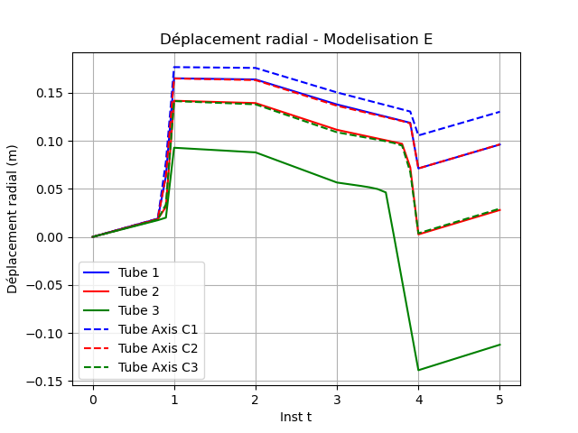
Fig. 7.1 Radial displacement#
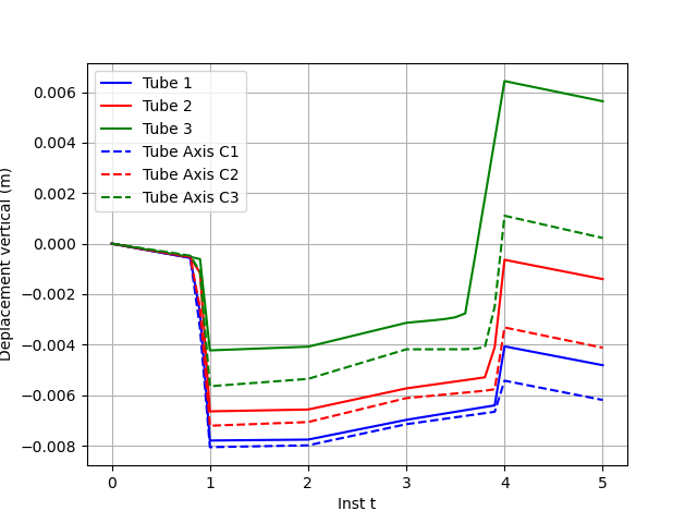
Fig. 7.2 Axial displacement#
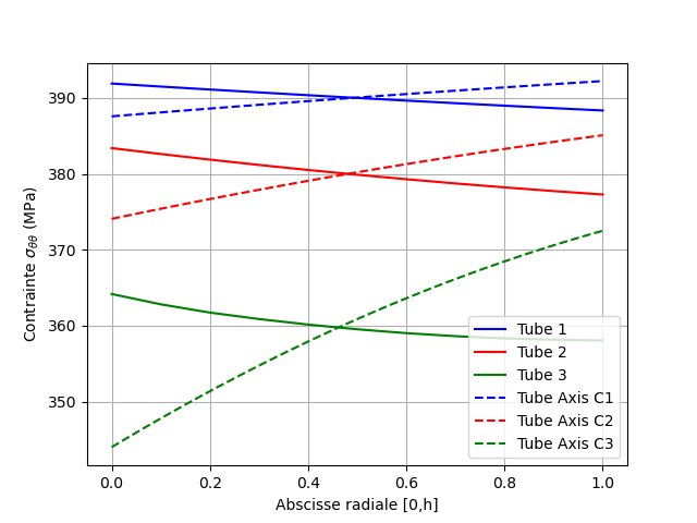
Fig. 7.3 Circumferential stresses at time 1#
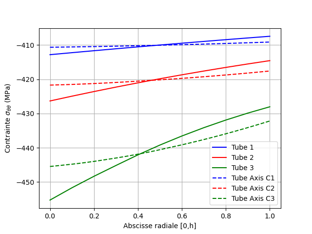
Fig. 7.4 Circumferential stresses at time 4#
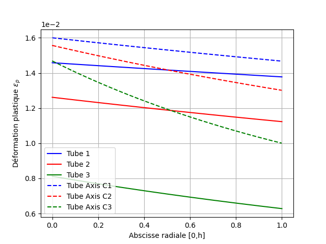
Fig. 7.5 Plastic deformation at instant 1#
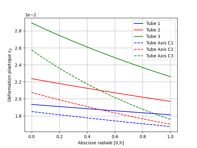
Fig. 7.6 Plastic deformation at instant 4#
7.5.2. Route 2#
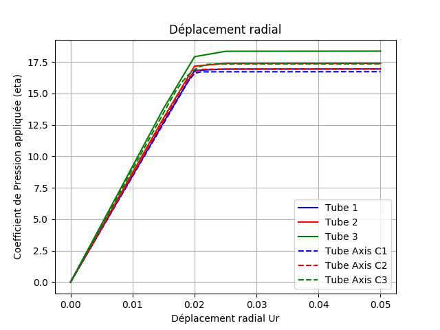
Fig. 7.7 Radial displacement#
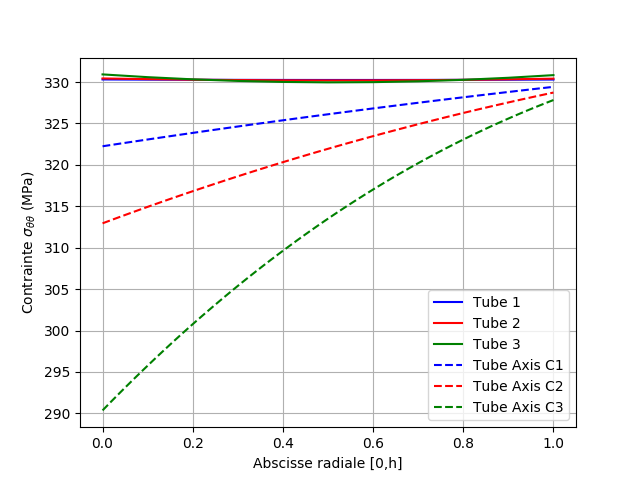
Fig. 7.8 Circumferential stresses at time 3#
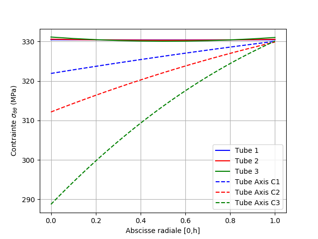
Fig. 7.9 Circumferential stresses at time 5#
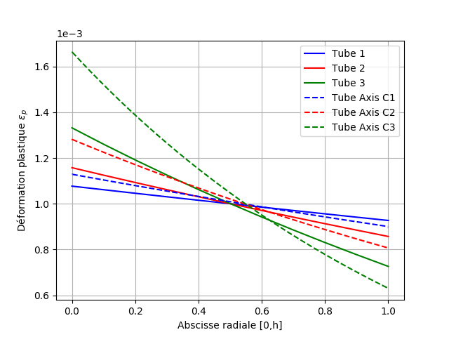
Fig. 7.10 Plastic deformation at instant 3#
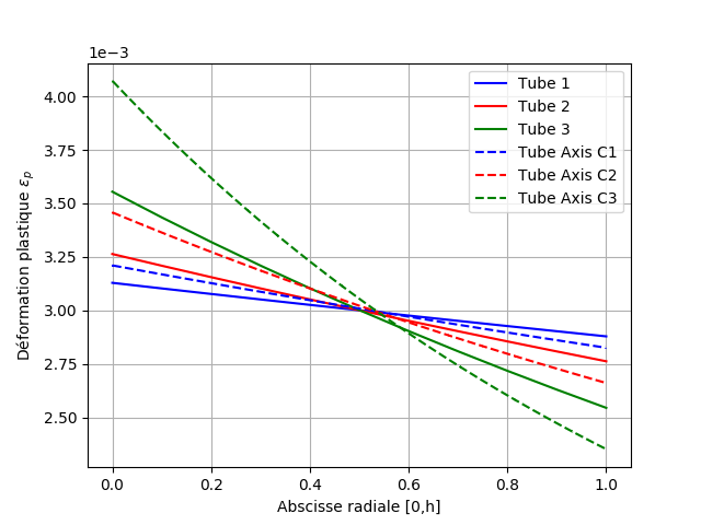
Fig. 7.11 Plastic deformation at instant 5#
7.6. Tested sizes and results#
The quantities tested are confronted with a non-regression criterion and also with their reference values produced by modeling A, see Modeling A.
7.6.1. Route 1#
Radial displacement on the mean surface (tube \(h/R = 1/20\))
WO displacement on average surface |
Tolerance (%) |
Instant t = 0.5 |
1 |
Instant t = 1. |
8 |
Instant t = 2. |
10 |
Instant t = 3. |
10 |
Instant t = 4. |
35 |
Instant t = 5. |
30 |
Radial displacement on the mean surface (tube \(h/R = 1/10\))
WO displacement on average surface |
Tolerance (%) |
Instant t = 0.5 |
2 |
Instant t = 1. |
15 |
Instant t = 2. |
16 |
Instant t = 3. |
20 |
Instant t = 4. |
100 |
Instant t = 5. |
75 |
Radial displacement on the mean surface (tube \(h/R = 1/5\))
WO displacement on average surface |
Tolerance (%) |
Instant t = 0.5 |
3 |
Instant t = 1. |
40 |
Instant t = 2. |
40 |
Instant t = 3. |
50 |
Instant t = 4. |
4000 |
Instant t = 5. |
500 |
Uniform axial displacement \(h/R = 1/20\) tube
DZ displacement on average surface |
Tolerance (%) |
Instant t = 0.5 |
3 |
Instant t = 1. |
4 |
Instant t = 2. |
4 |
Instant t = 3. |
3 |
Instant t = 4. |
30 |
Instant t = 5. |
35 |
Uniform axial displacement \(h/R = 1/10\) tube
DZ displacement on average surface |
Tolerance (%) |
Instant t = 0.5 |
6 |
Instant t = 1. |
10 |
Instant t = 2. |
10 |
Instant t = 3. |
10 |
Instant t = 4. |
85 |
Instant t = 5. |
70 |
Uniform axial displacement \(h/R = 1/5\) tube
DZ displacement on average surface |
Tolerance (%) |
Instant t = 0.5 |
12 |
Instant t = 1. |
30 |
Instant t = 2. |
30 |
Instant t = 3. |
30 |
Instant t = 4. |
600 |
Instant t = 5. |
5300 |
Average circumferential surface stress tube \(h/R = 1/20\)
Component SITT on an average area |
Tolerance (%) |
Instant t = 0.5 |
0.1 |
Instant t = 1. |
0.2 |
Instant t = 2. |
0.2 |
Instant t = 3. |
0.3 |
Instant t = 4. |
0.2 |
Instant t = 5. |
0.2 (ABSOLU) |
Average circumferential surface stress tube \(h/R = 1/10\)
Component SITT on an average area |
Tolerance (%) |
Instant t = 0.5 |
1 |
Instant t = 1. |
1 |
Instant t = 2. |
1 |
Instant t = 3. |
1 |
Instant t = 4. |
1 |
Instant t = 5. |
0.6 (ABSOLU) |
Average circumferential surface stress tube \(h/R = 1/5\)
Component SITT on an average area |
Tolerance (%) |
Instant t = 0.5 |
0.5 |
Instant t = 1. |
0.5 |
Instant t = 2. |
0.5 |
Instant t = 3. |
1 |
Instant t = 4. |
0.5 |
Instant t = 5. |
3 (ABSOLU) |
Cumulative plastic deformation on the average surface (tube \(h/R = 1/20\))
Component V1 on average area |
Tolerance (%) |
Instant t = 0.5 |
|
Instant t = 1. |
10 |
Instant t = 2. |
10 |
Instant t = 3. |
10 |
Instant t = 4. |
8 |
Instant t = 5. |
8 |
Cumulative plastic deformation on the average surface (tube \(h/R = 1/10\))
Component V1 on average area |
Tolerance (%) |
Instant t = 0.5 |
|
Instant t = 1. |
18 |
Instant t = 2. |
18 |
Instant t = 3. |
18 |
Instant t = 4. |
15 |
Instant t = 5. |
15 |
Cumulative plastic deformation on the average surface (tube \(h/R = 1/5\))
Component V1 on average area |
Tolerance (%) |
Instant t = 0.5 |
|
Instant t = 1. |
45 |
Instant t = 2. |
45 |
Instant t = 3. |
45 |
Instant t = 4. |
25 |
Instant t = 5. |
25 |
7.6.2. Path 2 monotonous internal pressure to ruin#
Radial displacement on the mean surface (tube \(h/R = 1/20\))
Coefficient factor of the applied pressure |
Tolerance (%) |
Instant t = 0.5 |
1 |
Instant t = 1. |
1 |
Instant t = 2. |
3 |
Instant t = 3. |
3 |
Instant t = 4. |
3 |
Instant t = 5. |
3 |
Radial displacement on the mean surface (tube \(h/R = 1/10\))
Coefficient factor of the applied pressure |
Tolerance (%) |
Instant t = 0.5 |
2 |
Instant t = 1. |
2 |
Instant t = 2. |
5 |
Instant t = 3. |
3 |
Instant t = 4. |
3 |
Instant t = 5. |
3 |
Radial displacement on the mean surface (tube \(h/R = 1/5\))
Coefficient factor of the applied pressure |
Tolerance (%) |
Instant t = 0.5 |
3 |
Instant t = 1. |
3 |
Instant t = 2. |
9 |
Instant t = 3. |
6 |
Instant t = 4. |
6 |
Instant t = 5. |
6 |
Average circumferential surface stress tube \(h/R = 1/20\). In particular: at the node of the upper edge of the tube, sector 1, layer 1.
Component SITT on an average area |
Tolerance (%) |
Instant t = 3. |
5 |
Instant t = 5. |
3 |
Average circumferential surface stress tube \(h/R = 1/10\). In particular: at the node of the upper edge of the tube, sector 1, layer 1.
Component SITT on an average area |
Tolerance (%) |
Instant t = 3. |
6 |
Instant t = 5. |
6 |
Average circumferential surface stress tube \(h/R = 1/5\). In particular: at the node of the upper edge of the tube, sector 1, layer 1.
Component SITT on an average area |
Tolerance (%) |
Instant t = 3. |
15 |
Instant t = 5. |
15 |
Cumulative plastic deformation on the average surface of tube \(h/R = 1/20\). In particular: at the node of the upper edge of the tube, sector 1, layer 1.
Component V1 on average area |
Tolerance (%) |
Instant t = 3. |
6 |
Instant t = 5. |
3 |
Cumulative plastic deformation on the average surface of tube \(h/R = 1/10\). In particular: at the node of the upper edge of the tube, sector 1, layer 1.
Component V1 on average area |
Tolerance (%) |
Instant t = 3. |
10 |
Instant t = 5. |
6 |
Cumulative plastic deformation on the average surface of tube \(h/R = 1/5\). In particular: at the node of the upper edge of the tube, sector 1, layer 1.
Component V1 on average area |
Tolerance (%) |
Instant t = 3. |
20 |
Instant t = 5. |
15 |
Generalized efforts (beam theory) at the nodes of the elements: N, VY, VZ, MT, MFY, MFZ. In particular: at the node at the bottom edge of tube \(h/R = 1/20\).
Instant component t = 2.5 |
worthiness |
N |
-2.37 |
VY |
|
VZ |
|
MT |
|
MFY |
|
MFZ |
Nodal forces (degrees of freedom of the beams and the 3 shell modes) at the nodes of the elements. In particular: at the nodes of tube \(h/R = 1/20\).
Instant component t = 2.5 |
worthiness |
DZ top edge |
|
WO top edge |
172.89 |
DZ middle |
|
WO middle |
691.58 |