4. B modeling#
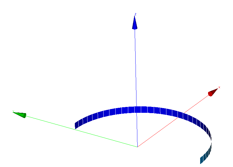
Modeling B is carried out with finite elements of plates from the DKT family on a half-circumference of the tube.
4.1. Characteristics of the mesh#
There are 36 quadrangle cells on the interval \(0,\pi\), in the \(Ox>0\) half-plane, but one cell along the axis of the tube \(Oz\). The mesh is symmetric with respect to the axis \(Oy = 0\), so as to have a node exactly on this axis in order to be able to compare with the movements of the axisymmetric mesh, see Modeling A. The command « MODI_MAILLAGE (ORIE_NORM_COQUE) » is carried out to ensure the correct orientation of the normals to the shell. There are 74 knots.
4.2. Modeling Characteristics and Loading Conditions#
There are 5 layers in the thickness, each with 3 sub-points for calculating stress fields and internal variables.
The lower edge is affected by total blocking in the axial direction \(Oz\); the upper edge is affected by a uniform connection on the translation in the axial direction in order to simulate kinematics identical to that of a very long tube. The values of the pressures applied are corrected to respect the exact metric of the internal and external walls, so that they are identical to those applied in modeling A. The keyword factor used in « AFFE_CHAR_MECA » is « FORCE_COQUE =_F (PRES =) ».
4.3. Characteristics of nonlinear static modeling#
The time step chosen is \(0.5\), fixed for all non-linear calculation steps; however, a cut is authorized in case of convergence failure, the criterion « RESI_GLOB_RELA » being set to \(10^{-6}\). The precision required to meet the plane stress condition is: « RESI_CPLAN_RELA =1e-06 ». Newton’s method uses the option « MATRICE =” TANGENTE “``. To calculate the limit pressure, load control is used by controlling the load by the radial movement of a node in the external wall. (To draw the curves, a calculation performed with a maximum time step of \(0.1\) is used.)
4.4. Post-treatment#
The post-processing of the radial displacement is done at any time in a node on the \(Oy=0\) axis. The post-processing of constraints and internal variables is done on a mesh and an integration point with its family of sub-points, close to the \(Ox\) axis.
4.4.1. Route 1#
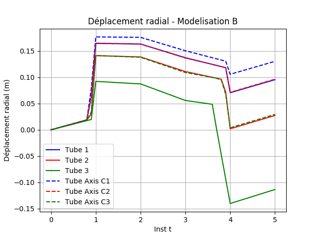
Fig. 4.1 Radial displacement#
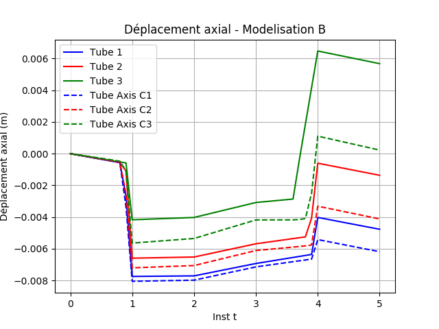
Fig. 4.2 Axial displacement#
It can be seen that the fields of stresses and internal variables (cumulative plastic deformations) are constant in the thickness of the tube at all times.
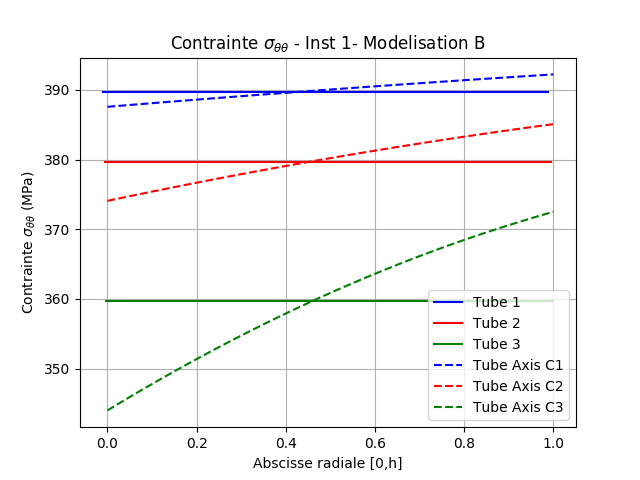
Fig. 4.3 Circumferential stresses at time 1#
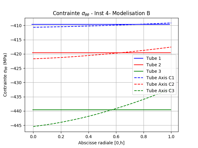
Fig. 4.4 Circumferential stresses at time 4#
The circumferential stresses in the wall are almost identical to the average of the reference circumferential stresses.
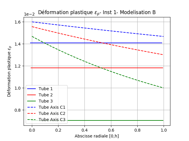
Fig. 4.5 Plastic deformation at instant 1#
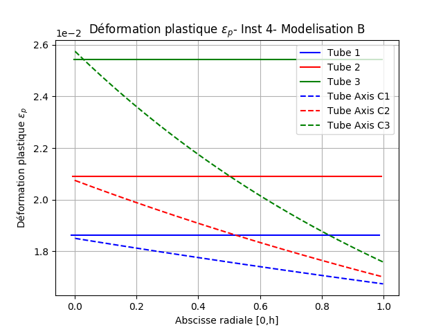
Fig. 4.6 Plastic deformation at instant 4#
The cumulative plastic deformations in the wall are either weaker or stronger than those of the reference solution, depending on the intensity of the loading. We can attribute this observation to the fact that pinch stresses were not taken into account in the plasticity criterion with modeling DKT.
4.4.2. Route 2#
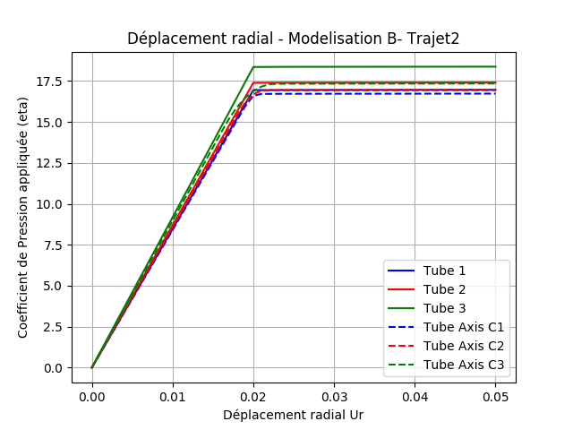
Fig. 4.7 Radial displacement#
It can be seen that the fields of stresses and internal variables (cumulative plastic deformations) are constant in the thickness of the tube at all times.
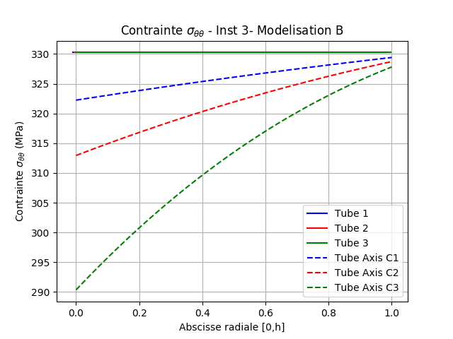
Fig. 4.8 Circumferential stresses at time 3#
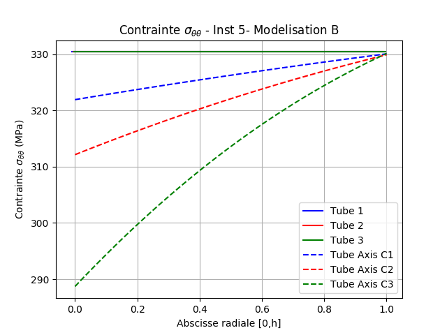
Fig. 4.9 Circumferential stresses at time 5#
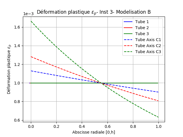
Fig. 4.10 Plastic deformation at instant 3#
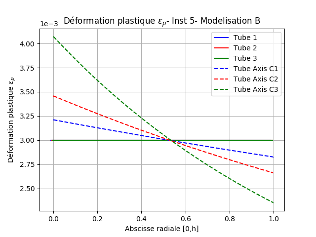
Fig. 4.11 Plastic deformation at instant 5#
4.5. Tested sizes and results#
The quantities tested are confronted with a non-regression criterion and also with the reference values produced by the A modeling, see Modeling A.
4.5.1. Route 1#
Radial displacement on the mean surface (tube \(h/R = 1/20\))
DX displacement on average surface |
Tolerance (%) |
Instant t = 0.5 |
1 |
Instant t = 1. |
10 |
Instant t = 2. |
10 |
Instant t = 3. |
10 |
Instant t = 4. |
35 |
Instant t = 5. |
30 |
Radial displacement on the mean surface (tube \(h/R = 1/10\))
DX displacement on average surface |
Tolerance (%) |
Instant t = 0.5 |
2 |
Instant t = 1. |
15 |
Instant t = 2. |
16 |
Instant t = 3. |
20 |
Instant t = 4. |
100 |
Instant t = 5. |
80 |
Radial displacement on the mean surface (tube \(h/R = 1/5\))
DX displacement on average surface |
Tolerance (%) |
Instant t = 0.5 |
3 |
Instant t = 1. |
40 |
Instant t = 2. |
40 |
Instant t = 3. |
50 |
Instant t = 4. |
4000 |
Instant t = 5. |
500 |
Uniform axial displacement \(h/R = 1/20\) tube
DZ displacement on average surface |
Tolerance (%) |
Instant t = 0.5 |
3 |
Instant t = 1. |
4 |
Instant t = 2. |
4 |
Instant t = 3. |
3 |
Instant t = 4. |
30 |
Instant t = 5. |
30 |
Uniform axial displacement \(h/R = 1/10\) tube
DZ displacement on average surface |
Tolerance (%) |
Instant t = 0.5 |
6 |
Instant t = 1. |
10 |
Instant t = 2. |
10 |
Instant t = 3. |
10 |
Instant t = 4. |
85 |
Instant t = 5. |
70 |
Uniform axial displacement \(h/R = 1/5\) tube
DZ displacement on average surface |
Tolerance (%) |
Instant t = 0.5 |
12 |
Instant t = 1. |
30 |
Instant t = 2. |
30 |
Instant t = 3. |
30 |
Instant t = 4. |
600 |
Instant t = 5. |
5300 |
Average circumferential surface stress tube \(h/R = 1/20\)
Component SIYY on an average area |
Tolerance (%) |
Instant t = 0.5 |
0.1 |
Instant t = 1. |
0.2 |
Instant t = 2. |
0.2 |
Instant t = 3. |
0.3 |
Instant t = 4. |
0.2 |
Instant t = 5. |
0.2 (ABSOLU) |
Average circumferential surface stress tube \(h/R = 1/10\)
Component SIYY on an average area |
Tolerance (%) |
Instant t = 0.5 |
0.1 |
Instant t = 1. |
0.2 |
Instant t = 2. |
0.2 |
Instant t = 3. |
1.0 |
Instant t = 4. |
0.2 |
Instant t = 5. |
0.8 (ABSOLU) |
Average circumferential surface stress tube \(h/R = 1/5\)
Component SIYY on an average area |
Tolerance (%) |
Instant t = 0.5 |
0.5 |
Instant t = 1. |
0.5 |
Instant t = 2. |
0.5 |
Instant t = 3. |
2.0 |
Instant t = 4. |
0.5 |
Instant t = 5. |
3.0 (ABSOLU) |
Cumulative plastic deformation on the average surface (tube \(h/R = 1/20\))
Component V1 on average area |
Tolerance (%) |
Instant t = 0.5 |
|
Instant t = 1. |
10 |
Instant t = 2. |
10 |
Instant t = 3. |
10 |
Instant t = 4. |
6 |
Instant t = 5. |
6 |
Cumulative plastic deformation on the average surface (tube \(h/R = 1/10\))
Component V1 on average area |
Tolerance (%) |
Instant t = 0.5 |
|
Instant t = 1. |
20 |
Instant t = 2. |
20 |
Instant t = 3. |
20 |
Instant t = 4. |
20 |
Instant t = 5. |
20 |
Cumulative plastic deformation on the average surface (tube \(h/R = 1/5\))
Component V1 on average area |
Tolerance (%) |
Instant t = 0.5 |
|
Instant t = 1. |
45 |
Instant t = 2. |
45 |
Instant t = 3. |
45 |
Instant t = 4. |
25 |
Instant t = 5. |
25 |
4.5.2. Path 2 monotonous internal pressure to ruin#
Pressure reached for tube \(h/R = 1/20\)
Coefficient factor of the applied pressure |
Tolerance (%) |
Instant t = 0.5 |
1 |
Instant t = 1. |
1 |
Instant t = 2. |
3 |
Instant t = 3. |
2 |
Instant t = 4. |
2 |
Instant t = 5. |
2 |
Radial displacement on the mean surface (tube \(h/R = 1/10\))
Coefficient factor of the applied pressure |
Tolerance (%) |
Instant t = 0.5 |
2 |
Instant t = 1. |
2 |
Instant t = 2. |
5 |
Instant t = 3. |
3 |
Instant t = 4. |
3 |
Instant t = 5. |
3 |
Radial displacement on the mean surface (tube \(h/R = 1/5\))
Coefficient factor of the applied pressure |
Tolerance (%) |
Instant t = 0.5 |
3 |
Instant t = 1. |
3 |
Instant t = 2. |
9 |
Instant t = 3. |
7 |
Instant t = 4. |
7 |
Instant t = 5. |
7 |
Average circumferential surface stress tube \(h/R = 1/20\)
Component SIYY on an average area |
Tolerance (%) |
Instant t = 3. |
3 |
Instant t = 5. |
3 |
Average circumferential surface stress tube \(h/R = 1/10\)
Component SIYY on an average area |
Tolerance (%) |
Instant t = 3. |
6 |
Instant t = 5. |
6 |
Average circumferential surface stress tube \(h/R = 1/5\)
Component SIYY on an average area |
Tolerance (%) |
Instant t = 3. |
15 |
Instant t = 5. |
15 |
Cumulative plastic deformation on the average surface (tube \(h/R = 1/20\))
Component V1 on average area |
Tolerance (%) |
Instant t = 3. |
15 |
Instant t = 5. |
8 |
Cumulative plastic deformation on the average surface (tube \(h/R = 1/10\))
Component V1 on average area |
Tolerance (%) |
Instant t = 3. |
25 |
Instant t = 5. |
15 |
Cumulative plastic deformation on the average surface (tube \(h/R = 1/5\))
Component V1 on average area |
Tolerance (%) |
Instant t = 3. |
45 |
Instant t = 5. |
27 |