3. Modeling A#
3.1. Characteristics of modeling#
The rotor is modelled by Euler beam elements (POU_D_E).
The crack is modelled by DYNA_VIBRA’s ROTOR_FISS feature. The law of crack behavior is entered by a function, itself determined on a bar with a unit diameter, independent of the geometry of the rotor (see modeling D).
DYNA_VIBRA calculates the transient on a modal basis. The latter is not orthogonal but consists on the one hand of the rotor beam modes with a closed crack (up to \(250\text{Hz}\)) and of the first 2 modes of beam with an open crack.
3.2. Characteristics of the mesh#
Number of stitches SEG2 |
21 |
3.3. Results: comparison between 3D and 1D calculations#
By plotting the movement of the end of the beam subjected to the moment of bending, it is observed that the crack opens and closes according to the angle of the crack bottom in relation to the direction of the moment exerted.
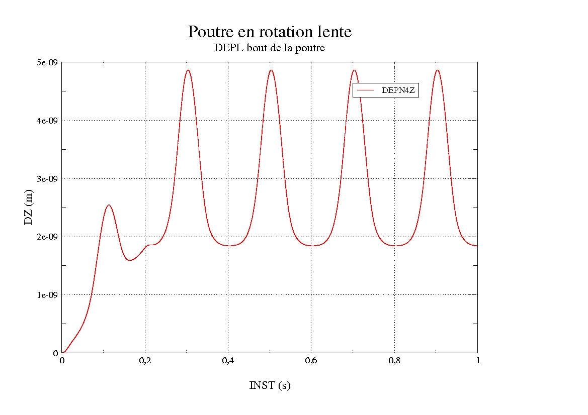
Figure 3: Displacement of the rotor end subjected to the bending moment
The neutral fiber of the beam is drawn for the closed crack (FIG. 4) and for the open crack (FIG. 5). They are comparable.
The table gives the numerical values tested in this test case. These are the movements at the end of the rotor for open crack and closed crack situations.
Identification |
Reference type |
Reference value |
Tolerance |
Open crack - \(\mathit{DZ}\) at the end |
“AUTRE_ASTER” |
4.52765E-09 |
|
Open crack - \(\mathit{DZ}\) at the end |
“NON_REGRESSION” |
4.8308805E-09 |
|
Crack closed - \(\mathit{DZ}\) at the end |
“AUTRE_ASTER” |
1.77757E-09 |
|
Crack closed - \(\mathit{DZ}\) at the end |
“NON_REGRESSION” |
1.8442025E-09 |
|
Table 3.3-1 : Summary of tested results
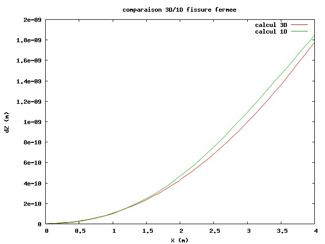
Figure 4: Comparison of 1D/3D closed crack
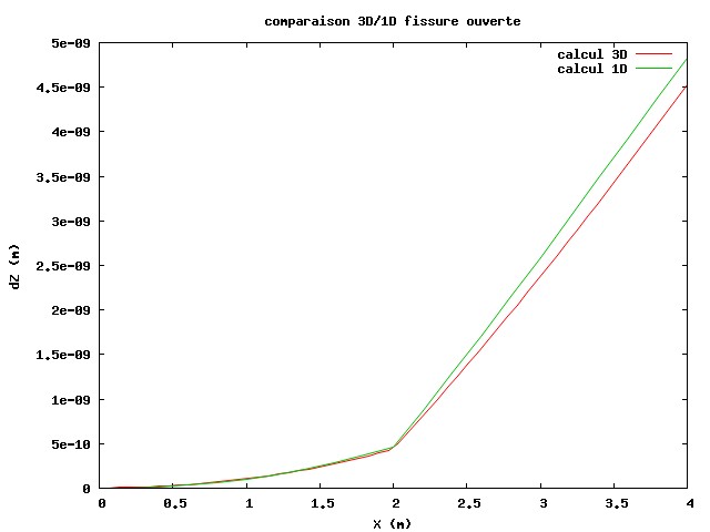
Figure 5:1D/3D open crack comparison