1. Description#
1.1. Geometry#
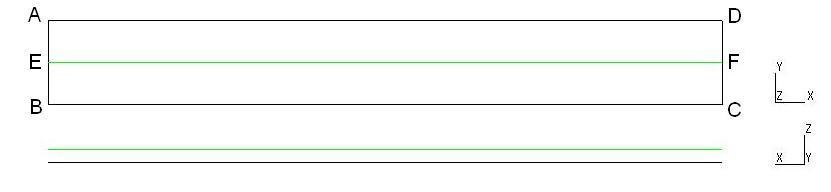
The study model is a rectangular plate with length \(L\mathrm{=}\mathrm{4m}\), width \(l\mathrm{=}\mathrm{0.5m}\) and thickness \(t\mathrm{=}\mathrm{0.2m}\). A flexure reinforcement composed of a single frame crosses the plate halfway through the plate and is offset by a distance \({e}_{z}\mathrm{=}\mathrm{0.075m}\) from the median plane of the plate along the axis \(z\). From a geometric point of view, we only know the area of the right-hand section of bar \(A\mathrm{=}{\mathrm{0.00015m}}^{2}\). The figure below shows the cable position for the study model. The median plane of the plate is defined by the rectangle \(\mathit{ABCD}\) and the cable by the segment \(\mathit{EF}\).
1.2. Material properties#
The properties of concrete for the plate and steel for the cable are listed in the table
next.
Material |
Concrete |
Steel |
Young Module |
\(4\mathrm{\times }{10}^{10}\mathit{Pa}\) |
|
Fish Coefficient |
\(0.0\) * |
\(0.0\) |
Density |
\(2500\mathit{kg}\mathrm{/}{m}^{3}\) |
|
Elastic limit stress |
\(n\mathrm{/}a\) |
|
*It is subsequently justified that the study model can be assimilated to a beam and that a Poisson’s ratio for concrete equal to \(0.0\) will be taken.
1.3. Boundary conditions and loads#
The side defined by the segment AB of the plate is embedded, all the degrees of freedom on this side are blocked and the other edges are left free to allow it to be configured in a beam-like manner. The order in which the loads are applied is defined as follows.
1.3.1. Loading 1:#
It corresponds to the tension of the cable. A voltage equal to \(3.75\mathrm{\times }{10}^{5}N\) is imposed in the cable, and only the \(F\) node of the cable located at the free edge of the plate is active. Tensile losses due to steel relaxation and anchoring recoil are neglected.
1.3.2. Loading 2:#
The second load applies pressure \({P}_{0}\mathrm{=}{10}^{5}\mathit{Pa}\), carried by the axis \(\mathrm{-}z\), all over the plate.
1.4. Main stages of testing#
The macro command DEFI_CABLE_BP is used to obtain the kinematic relationships between the plate and the cable as well as the load related to the tension in the cable. Only cable node \(F\) is considered active.
The macro-command CALC_PRECONT is then launched to prestress the plate using the given cable tension.
The STAT_NON_LINE command is also used to apply pressure loading to the plate. The maximum value of the displacement on the free edge of the plate is then extracted at node \(D\), in order to compare them with the reference values and thus to validate the tension of the prestress cables for the shell elements.