1. Reference problem#
1.1. Geometry#
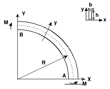
Radius of curvature |
\(R\mathrm{=}0.3m\) |
Profile height |
\(h\mathrm{=}0.015m\) |
Profile width |
\(b\mathrm{=}0.002m\) |
Section |
\(S\mathrm{=}\mathit{bh}\) |
1st flexural inertia |
\({I}_{X}\mathrm{=}{\mathit{bh}}^{3}\mathrm{/}12\) |
2nd flexural inertia |
\({I}_{Y}\mathrm{=}{\mathit{hb}}^{3}\mathrm{/}12\) |
Torsional inertia |
\(J\mathrm{=}{\mathit{hb}}^{3}\mathrm{/}3\) |
1.2. Material properties#
Young’s module |
\(E\mathrm{=}7.E10N\mathrm{/}{m}^{2}\) |
Poisson’s Ratio |
\(\nu \mathrm{=}0.3\) |
Sliding module |
\(G\mathrm{=}E\mathrm{/}2(1+\nu )\) |
1.3. Boundary conditions and loading#
The beam is double-supported. The section is prevented from twisting at the \(A\) and \(B\) ends. To respect the hypotheses of the theoretical model taken as a reference, it is important that the moment is constant and that the normal force is zero along the beam. This is why we leave the \(u\) movement free according to \(X\) at point \(B\). The boundary conditions are:
At point \(A\): \(u\mathrm{=}v\mathrm{=}w\mathrm{=}0\); \({\Phi }_{Y}\mathrm{=}0\)
At point \(B\): \(v\mathrm{=}w\mathrm{=}0\); \({\Phi }_{X}\mathrm{=}0\)
The initial state of stress that allows the stability analysis to be carried out is obtained by imposing a moment of bending around the \(Z\) axis, at points \(A\) and \(B\): \(M\mathrm{=}1\mathit{Nm}\)
1.4. Initial conditions#
Not applicable in static stability analysis.