3. Modeling A#
3.1. Characteristics of modeling#
The arch is meshed using POU_D_E straight beam elements.
Boundary conditions:
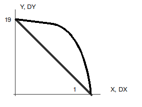
At point \(A\) such as \(X\mathrm{=}R\), \(Y\mathrm{=}0\): \(\mathit{DX}\mathrm{=}\mathit{DY}\mathrm{=}\mathit{DZ}\mathrm{=}0\), and \(\mathit{RY}\mathrm{=}0\)
At point \(B\) such as \(X\mathrm{=}0\), \(Y\mathrm{=}R\): \(\mathit{DY}\mathrm{=}\mathit{DZ}\mathrm{=}0\), and \(\mathit{RX}\mathrm{=}0\)
For static analysis, unit moments around \(Z\) are defined at nodes 1 and 19.
3.2. Characteristics of the mesh#
Number of knots: 19
Number of stitches: 18 POU_D_E
3.3. Tested sizes and results#
Critical load
3.3.1. CALC_MODES with SOLVEUR_MODAL =_F (METHODE = “SORENSEN”)#
Identification Critical load number |
Reference |
Code_Aster |
\(\text{\%}\) difference |
1 |
2.86074 |
2.75137 |
3.823 |
2 |
8.63207 |
8.30613 |
3.776 |
3 |
-8.78382 |
-8.39554 |
4.420 |
4 |
14.4147 |
13.93216 |
3.348 |
5 |
-14.5551 |
-14.01104 |
3.738 |
3.3.2. CALC_MODES with OPTION = “PROCHE”#
Identification Critical load number |
Reference |
Code_Aster |
\(\text{\%}\) difference |
1 |
2.86074 |
2.75137 |
3.823 |
2 |
8.63207 |
8.30613 |
3.776 |
3 |
-8.78382 |
-8.39554 |
4.420 |
4 |
14.4147 |
13.93216 |
3.348 |
5 |
-14.5551 |
-14.01104 |
3.738 |
3.3.3. CALC_MODES with OPTION = “SEPARE”#
Identification Critical load number |
Reference |
Code_Aster |
\(\text{\%}\) difference |
1 |
2.86074 |
2.75137 |
3.823 |
2 |
8.63207 |
8.30613 |
3.776 |
3 |
-8.78382 |
-8.39554 |
4.420 |
4 |
14.4147 |
13.93216 |
3.348 |
5 |
-14.5551 |
-14.01104 |
3.738 |
3.3.4. CALC_MODES with OPTION = “AJUSTE”#
Identification Critical load number |
Reference |
Code_Aster |
\(\text{\%}\) difference |
1 |
2.86074 |
2.75137 |
3.823 |
2 |
8.63207 |
8.30613 |
3.776 |
3 |
-8.78382 |
-8.39554 |
4.420 |
4 |
14.4147 |
13.93216 |
3.348 |
5 |
-14.5551 |
-14.01104 |
3.738 |