2. B modeling#
2.1. Geometry and modeling#
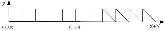
The mesh is composed of:
7 QUAD4 meshes on which the DKT, DST, Q4G, Q4G, DKTG, Q4GG, GRILLE_EXCENTRE, GRILLE_MEMBRANE and MEMBRANE models are assigned.
7 TRIA3 meshes on which the DKT, DST, Q4G, Q4G, DKTG, Q4GG, GRILLE_EXCENTRE and GRILLE_MEMBRANE models are assigned.
2.2. Orientation of the local coordinate system#
In order to define the local coordinate system for these elements, the ANGL_REP keyword from the AFFE_CARA_ELEM operator is used (see [U4.42.01]).
The table above gives the orientations chosen for each element:
Cases |
ANGL_REP |
|
Grids |
ANGL_REP |
|
Membranes |
ANGL_REP |
|
2.3. Calculation of local landmarks#
The local landmarks are formed by the vectors \(x\), \(y\), and \(z\).
For shells and grids the vector \(z\) is defined by the normal exiting to the shell. In our example we will have \(z=\left(\frac{-\sqrt{2}}{2},\frac{\sqrt{2}}{2},0\right)\).
The value given to ANGL_REP defines a vector whose projection on the tangential plane to the element gives the vector \(x\). So the values in the example are \(x=\left(\mathrm{0.5,0}\mathrm{.5,}\frac{\sqrt{2}}{2}\right)\) and \(y=\left(-\mathrm{0.5,}-\mathrm{0.5,}\frac{\sqrt{2}}{2}\right)\).
2.4. Tested sizes#
The tested results are shown in the following table:
MAILLE |
Vector |
Component |
Reference Value |
Tolerance |
|
DKT4 |
|
|
|
|
|
DKT3 |
|
|
|
|
|
DST4 |
|
|
|
|
|
DST3 |
|
|
|
|
|
Q4G4 |
|
|
|
|
|
DKTG4 |
|
|
|
|
|
GRME3 |
|
|
|
|
|
Q4 GG3 |
|
|
|
|
|
GREX4 |
|
|
|
|
|
MEMB4 |
|
|
|
|
|
DKT4 |
|
|
|
|
|
DKT3 |
|
|
|
|
|
DST3 |
|
|
|
|
|
Q4G4 |
|
|
|
|
|
GRME3 |
|
|
|
|
|
Q4 GG3 |
|
|
|
|