1. Reference problem#
1.1. Geometry#
The structure is obtained by rotating around the Z axis, from the section shown in [Figure].

Figure 1.1-a: Structure section
1.2. Material properties#
The study is carried out using linear thermal methods; only thermal characteristics are necessary to define the material.
Isotropic thermal conductivity: \(\lambda =15.0W/\mathrm{m.k}\)
1.3. Boundary conditions and loads#
The study is carried out using linear thermal methods, the conditions on the temperatures imposed are represented in [Figure], the flow conditions and the heat exchanges are indicated in [Figure].

Figure 1.3-a: View from above, with the imposed temperature conditions.
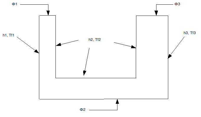
Figure 1.3-b: Sectional view, with flow conditions and heat exchanges.
Flow conditions:
\({\phi }_{1}=10.0W/{m}^{2}\)
\({\phi }_{2}=0.0W/{m}^{2}\)
\({\phi }_{3}=30.0W/{m}^{2}\)
Convective exchange conditions:
\({h}_{1}=350.0W/{m}^{2}k\) \({\mathrm{tf}}_{1}=300.0°C\)
\({h}_{2}=400.0W/{m}^{2}k\) \({\mathrm{tf}}_{2}=275.0°C\)
\({h}_{3}=600.0W/{m}^{2}k\) \({\mathrm{tf}}_{3}=310.0°C\)
Imposed temperature conditions:
\({\mathrm{Temp}}_{1}=250.0°C\)
\({\mathrm{Temp}}_{2}=160.0°C\)
1.4. Initial conditions#
Not applicable.