3. Modeling A#
3.1. Characteristics of modeling#
The aim of this modeling is to obtain the solution to the thermal problem from the calculation carried out on 1/8th of the structure.
The test case is carried out as follows:
reading the mesh, 1/8th structure, from the file in « MED » format, command LIRE_MAILLAGE.
reading the temperature field from the file in « MED » format, command LIRE_CHAMP.
creating a result from the field previously read, command CREA_RESU.
creating a model from the mesh previously read, command AFFE_MODELE.
creation of a model for the groups of cells that belong to the symmetry plane, command AFFE_MODELE (see note 1).
reading the mesh, 1/8th structure, from the file in « MED » format and modifying the mesh by symmetry with respect to the plane (\({\pi }_{\mathrm{sym}}\)) defined by:
AXE_1 = \((\mathrm{1.0,}1.0,0.0)\), AXE_2 = \((0.0,0.0,-1.0)\), POINT = \((0.0,0.0,0.0)\)
commands LIRE_MAILLAGE and MODI_MAILLAGE.
reading the temperature field from the file in « MED » format, command LIRE_CHAMP.
creating a result from the field previously read, command CREA_RESU.
creating a model from the symmetric mesh, command AFFE_MODELE.
reading the mesh representing 1/4 of the structure, command LIRE_MAILLAGE.
creating a model from the mesh previously read, command AFFE_MODELE.
projection of the 3 results created from the solution calculated on 1/8th of the structure, command PROJ_CHAMP with the keyword DISTANCE_MAX.
extraction of the temperature fields of the 3 results from the projection, command CREA_CHAMP.
creation of a null field on the model built on 1/4 of the structure, command CREA_CHAMP (see note no. 2).
combination of all fields, command CREA_CHAMP/OPERATION =” ASSE “
creating a result from the combination of fields, CREA_RESU.
Note 1:
In this test case, nodes in the mesh, [Figure ], belong to the symmetry plane \({\pi }_{\mathrm{sym}}\). For these nodes, the projection of the temperature field will therefore be counted twice. To avoid accumulating the temperature field one too many times, one solution is to create a model containing only these nodes and to perform the projection on the complete mesh. This projected field will then be subtracted using the command CREA_CHAMP/OPERATION =” ASSE “ .
Note #2:
Projecting fields using the command PROJ_CHAMP and the keyword DISTANCE_MAXpermet not to create a field on nodes that are not contained in one of the elements of the initial mesh and that are at a distance greater than DISTANCE_MAXde the closest element. When combining fields using the CREA_CHAMP/OPERATION =” ASSE “command, the first field at the nodes is taken as a reference. If the field is incomplete, as in our case, the combination will not give the expected result. The solution is therefore to create a null field on the whole model and to use it as a reference field. *
3.2. Characteristics of the mesh#
The projection of the temperature field calculated on 1/8th of the structure (mesh of the [Figure1.1-a]) is projected onto the model constructed from the mesh of 1/4 of the structure [Figure3.2-a]).

|

|
Figure 3.2-a: 1/4 mesh size of the structure.
3.3. Tested sizes and results#
The test is carried out on the temperature field.
From the result obtained by projection and combination on 1/4 of the structure, the temperature field TEMP1 is extracted. From the result calculated on 1/4 of the structure, the 2nd temperature field TEMP2 is extracted. These 2 fields are subtracted using the command CREA_CHAMP/OPERATION =” ASSE “, and the test is performed on the maximum and minimum value of the resulting field. At all points of the structure, we must have TEMP1 = TEMP2, so the field resulting from the command CREA_CHAMP/OPERATION =” ASSE “must be zero at all points.
Values tested |
Reference |
Code_Aster |
Precision |
Maximum |
0.0 |
2.694E-05 |
1.0E-4 |
Minimum |
0.0 |
-1.808E-05 |
1.0E-4 |
The [Figure] shows the map of the differences between the two temperature fields obtained during this test case.
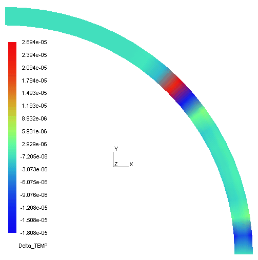
Figure 3.3-a: Temperature difference map.