4. Boundary condition modeling#
4.1. Blockages & Forces & Pressures#
The application of boundary conditions such as blockages, forces, pressures is done in a conventional manner with the operator AFFE_CHAR_MECA [AFFE_CHAR_MECA].
The models involve eccentric plate elements for which the orientation of the normal to the meshed surface will define the eccentricity and make it possible to apply a possible pressure load. It will therefore be necessary to be consistent, cf. operators AFFE_CHAR_MECA [AFFE_CHAR_MECA], AFFE_CARA_ELEM [AFFE_CARA_ELEM].
4.2. Liaisons#
The eccentricity of the plates makes it possible to account for the arrangement of the various elements (sheets, reinforcement sheets, concrete) in relation to each other. This functionality allows code_aster to calculate the homogenized characteristics of walls and floors, both linear and non-linear.
An important point in modeling the structure is to best describe the connections between the various elements of the structure: the connection between 2 walls, the connection between a veil and a floor,… These connections can be described in several ways:
When meshes are coincident. The nodes as well as the edges and/or faces of the elements are common. The degrees of freedom carried by the knots must be consistent. When assembling the system of equations, code_aster takes into account the degrees of freedom carried by the various nodes. The meshing as well as the assignment of the finite element models is sufficient for the realization of this connection.
For example, this solution can be used when modeling a floor to model the connection between the stiffeners and the bottom sheet.
This solution imposes constraints when creating meshes (mesh size,…) which can be difficult to implement.
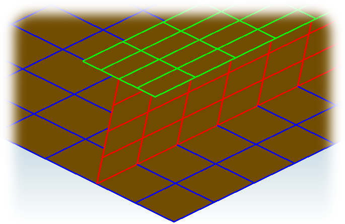
Figure 4.2-a : Coincident meshes, floor stiffeners.
When meshes are not coincident. In this case, there are no nodes, edges, or faces in common between the elements you want to connect. It is necessary to use a code_aster feature to link meshes. The operator that allows this link is AFFE_CHAR_MECA [AFFE_CHAR_MECA] with the keyword LIAISON_ELEM.
Excerpt of commands for the link between 2 elements:
LIAISON_MAIL = (
# Floor: Pb1, Junction: Voil1
_F (GROUP_MA_ESCL = “FloorSheet”,
GROUP_MA_MAIT = “Veil”, TYPE_RACCORD = “COQUE”, ), ),
),
A particularity of this connection is that the meshes to be connected do not need to be perfectly « in front » of each other. But to ensure a « realistic » connection, the refinement of the meshes to be linked must be close.
This « way of doing things » is not recommended:
◦ When a structural element that is part of the connection is modeled using offset plates. The eccentricity will not be taken into account, as it is necessary to provide additional information (see § 4.3 on eccentric connections).
◦ When there are « thick » elements in the junction that are modeled by plate elements. It is the average surfaces that are meshed and in the area of intersection of the structural elements, the question arises of the justification of the modeling (cf. appendice§ 7.2).
4.3. Off-center connections#
When elements use the concept of eccentricity (plates and grids using finite elements such as DKT and GRILLE_EXCENTRE) and are connected together, it is necessary to ask the question of modeling the connections. This chapter discusses a way to « best » describe connections by taking into account the eccentricities of the elements in relation to each other.
4.3.1. The need to take into account eccentricities#
The figure shows a case study that highlights the need to take eccentricities into account. This case is modelled with DKT without eccentricities that will serve as a reference, and with eccentric DKT. It is part of the code_aster [V1.01.419] verification base.
The figure shows the displacements and the stresses obtained during an elastic analysis with DKT without eccentricity, this case will be our reference solution.
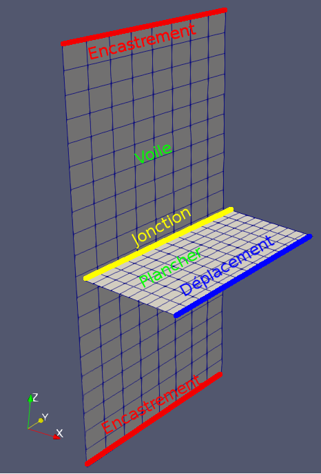
Figure 4.3.1-a: EF model of a link between sail and floor. |
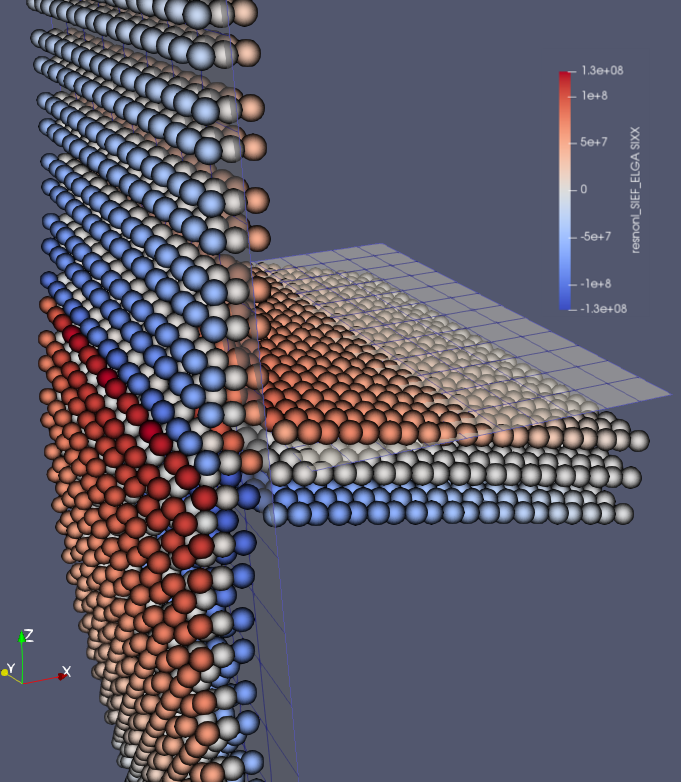
Figure 4.3.1-b: Connection between sail and floor. Reference solution. |
The principle of validation is to use offset DKT: to mesh the horizontal plate offset in the « -z » direction by a value \(\mathrm{\delta }\text{z}=50\mathit{cm}\) [1] _ and then to offset it by entering in the command file the keyword EXCENTREMENT of the AFFE_CARA_ELEM command with a value of \(\mathrm{\delta }\text{z}\) in the « +z » direction. We therefore represented the horizontal plate by a mesh offset by \(-\mathrm{\delta }\text{z}\) which was then offset by a value \(\mathrm{\delta }\text{z}\). If all goes « well » the solution of this problem must correspond to the solution of the reference problem, which is neither offset nor off-center.
The figures show the results (under 2 different observation points) obtained without taking into account the eccentricity in the connection between the veil and the floor. It can be noted that the stresses in the floor are comparable to those obtained with the reference model, figure. On the other hand, the results obtained in the veil both for constraints and movements and therefore for generalized efforts, are false.
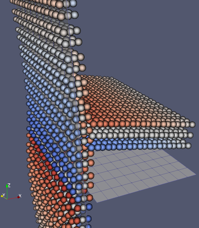
Figure 4.3.1-c: Connection between sail and floor. Solution obtained without an eccentric bond (view 1). |
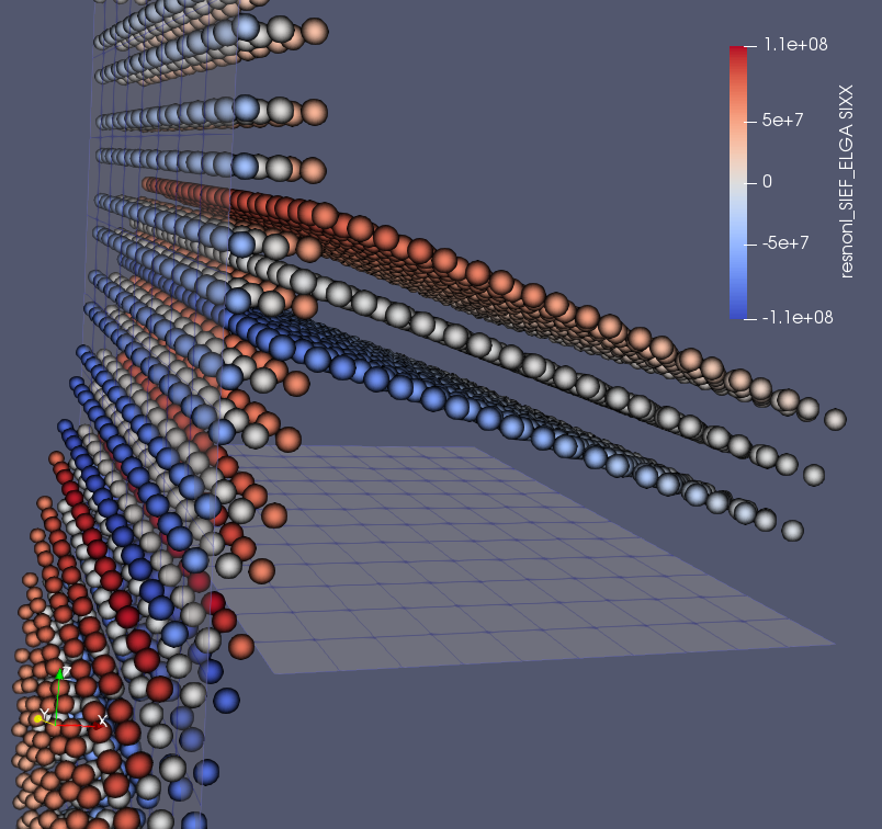
Figure 4.3.1-d: Connection between sail and floor. Solution obtained without an eccentric bond (view 2). |
This difference comes from the fact that the relationships describing the kinematics of the connection are written between the « non-eccentric » nodes of the floor and the meshes of the veil which are facing each other. Eccentricity is well taken into account when writing the kinematics of finite elements and their equilibrium equations but does not in any way modify the position of the support mesh. As a result, the AFFE_CHAR_MECA command with the LIAISON_MAIL option does not take eccentricity into account.
4.3.2. Off-center links in code_aster#
When the links concern eccentric elements and when it is desired to take account of this eccentricity in the kinematic equations of the link, it is then necessary to give code_aster the information to write these equations correctly taking into account the real position of the elements in relation to each other and no longer only from the support mesh.
The operator that makes it possible to take into account the eccentricity of the links is always AFFE_CHAR_MECA [AFFE_CHAR_MECA] with the keyword factor LIAISON_ELEM, with the addition of the possibility of offsetting the GROUP_MA_MAITet /or GROUP_MA_ESCL. This eccentricity is filled in using the keywords TRANSF_GEOM_MAIT and TRANSF_GEOM_ESCL. They work and use the same tools as the PROJ_CHAMP [PROJ_CHAMP] command with the TRANSF_GEOM_1et TRANSF_GEOM_2 keywords.
The figures and make it possible to compare the results obtained with the reference solution and those obtained with the eccentric connection. The constraints, the movements as well as the generalized efforts are the same. This test is part of the code_aster [V1.01.419] validation base.
|
Figure 4.3.2-a: Connection between sail and floor. Reference solution. |
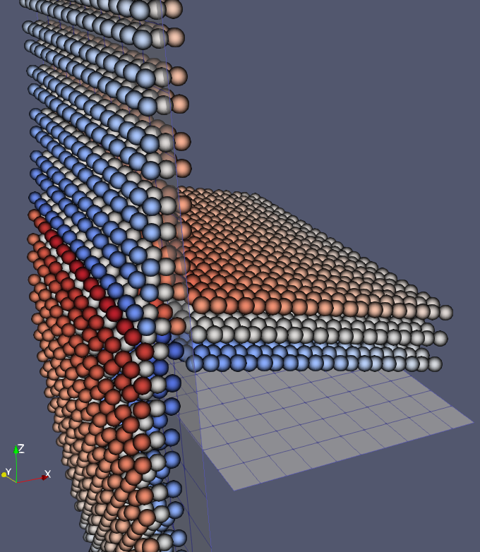
Figure 4.3.2-b: Connection between sail and floor. Solution obtained with the eccentric connection. |
For this example, the eccentricity is taken into account simply by specifying the temporary transformation of the coordinates of the slave nodes, as follows:
TRANSF_GEOM_ESCL = ( TrfXe, TrfyE, RfZe ),
For more details see § 7.3 or test case ZZZZ419 [V1.01.419].
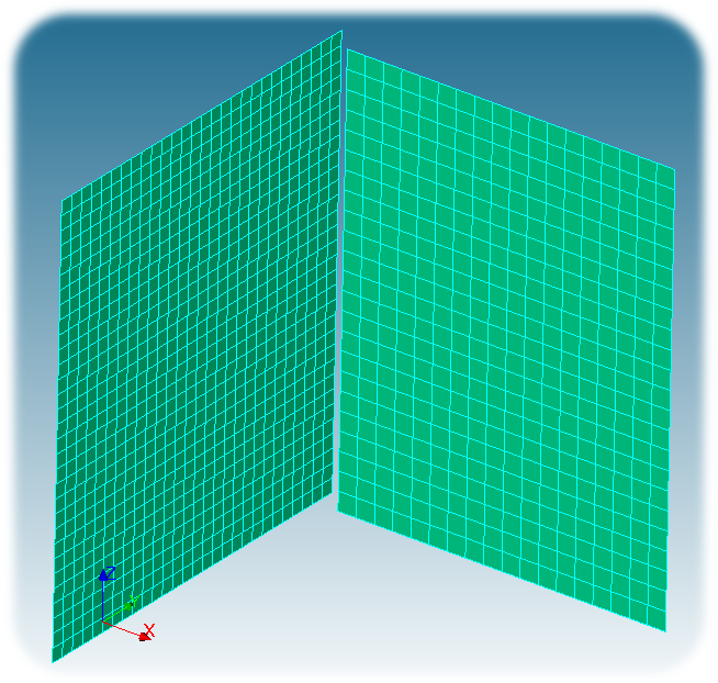
4.4. Example of a connection between 90° sails#
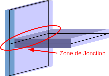
The figure shows CAO of a junction between 2 sails. The mesh of the structure will be positioned on the average surface of the veil. The eccentric elements will therefore be the sheets of the sails.
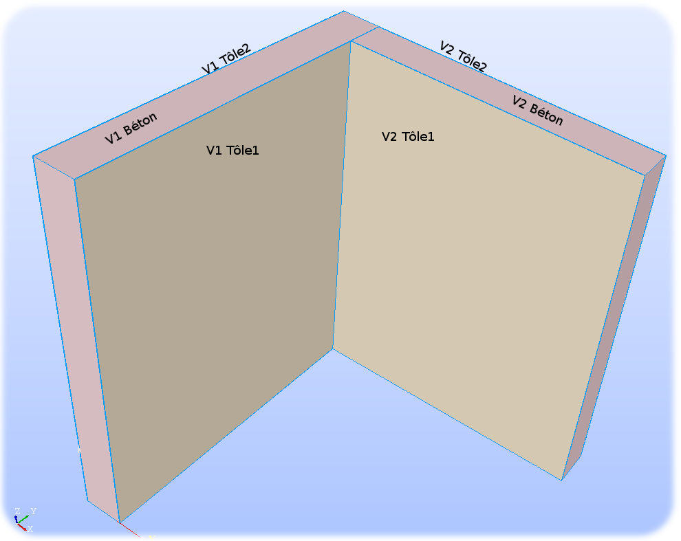
Figure 4.4-a : CAO of a junction between 2 sails.
The assignment of characteristics (thicknesses, number of layers, eccentricity) is done using the AFFE_CARA_ELEM [AFFE_CARA_ELEM] command. The eccentricity sign for sail sheets is a function of the sense of normal. For the 2 sails, the normal is oriented from sheet 1 to sheet 2. The eccentricity is therefore negative for sheet 1 and positive for sheet 2.
CareLem = AFFE_CARA_ELEM ( … ,
COQUE = (
# Sail: V1
_F (GROUP_MA =( “V1 GBeton “, )) ), EPAIS = 4.840e-01, VECTEUR =( 0.0, 0.0, 1.0 ),
COQUE_NCOU = 7, INER_ROTA = “OUI”, )
_F (GROUP_MA =( “V1 GTole1 “, )) ), EPAIS = 8.000e-03, VECTEUR =( 0.0, 0.0, 1.0 ),
EXCENTREMENT = -2.460e-01, INER_ROTA = “OUI”, ), ),
_F (GROUP_MA =( “V1 GTole2 “, )) ), EPAIS = 8.000e-03, VECTEUR =( 0.0, 0.0, 1.0 ),
EXCENTREMENT = 2.460e-01, INER_ROTA = “OUI”, ), ),
# Sail: V2
_F (GROUP_MA =( “V2 GBeton “, )) ), , EPAIS =**4.840e-01,** VECTEUR =( 0.0, 0.0, 1.0) **,
COQUE_NCOU = 7, INER_ROTA = “OUI”, )
_F (GROUP_MA =( “V2 GTole1 “, )) ,) , EPAIS =**8.000e-03,** VECTEUR =( 0.0, 0.0, 1.0) **,
EXCENTREMENT = -2.460e-01, INER_ROTA = “OUI”, ), ),
_F (GROUP_MA =( “V2 GTole2 “, )) ,) , EPAIS =**8.000e-03,** VECTEUR =( 0.0, 0.0, 1.0) **,
EXCENTREMENT = 2.460e-01, INER_ROTA = “OUI”, ), ),
),
)
The definition of the connection between the walls V1 and V2 may or may not take into account the eccentricity of the elements. This choice is to be made when using LIAISON_MAIL from the AFFE_CHAR_MECA [AFFE_CHAR_MECA] command and remains at the discretion of the modeler.
Below is an order excerpt, which defines the connection between the 2 sails without taking into account the eccentricity.
CLIM1 = AFFE_CHAR_MECA ( … ,
LIAISON_MAIL = (
# Sail: V2, Junction Jct1 from Bord3 to V1
_F (GROUP_MA_ESCL = “V2 GBord3 “, GROUP_MA_MAIT = “V1 GBeton”, TYPE_RACCORD = “COQUE”,
DISTANCE_ALARME = 2.750e-01, DISTANCE_MAX = 2.750e-01, ),
),
)
Below is an order excerpt, which defines the connection between the 2 walls taking into account the eccentricity of the sheets. This eccentricity is taken into account in the kinematic equations that describe the bond using the keywords TRANSF_GEOM_MAIT and TRANSF_GEOM_ESCL.
CLIM2 = AFFE_CHAR_MECA ( … ,
LIAISON_MAIL = (
# Sail: V2, Junction Jct1: Connection of Edge3 with V1 Tole1
_F (GROUP_MA_ESCL = “V2 GTole1Bord3 “, GROUP_MA_MAIT = “V1 GTole1”, TYPE_RACCORD = “COQUE”,
TRANSF_GEOM_ESCL =( FV2GTole1DX, FV2GTole1DY,, FV2GTole1DZ ),
TRANSF_GEOM_MAIT =( FV1GTole1DX, FV1GTole1DY,, FV1GTole1DZ ),
DISTANCE_ALARME = 1.50e-02, DISTANCE_MAX = 1.50e-02, ),
_F (GROUP_MA_ESCL = “V2 GTole2Bord3 “, GROUP_MA_MAIT = “V1 GTole1”, TYPE_RACCORD = “COQUE”,
TRANSF_GEOM_ESCL =( FV2GTole2DX, FV2GTole2DY,, FV2GTole2DZ ),
TRANSF_GEOM_MAIT =( FV1GTole1DX, FV1GTole1DY,, FV1GTole1DZ ),
DISTANCE_ALARME = 1.50e-02, DISTANCE_MAX = 1.50e-02, ),
),
)
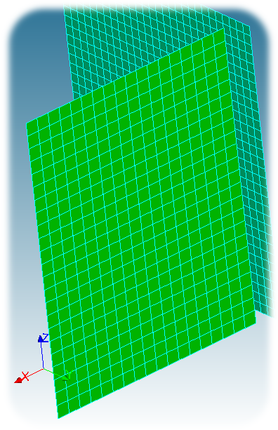
Whether you describe the connection with or without the eccentricities, it has no impact on the mesh. The figure shows the mesh of the 2 sails. The plate elements are located on the middle plane of the walls and are therefore not coincident. Although connection CLIM1ne takes into account the eccentricity of the sheets, it takes into account the relative position of the average planes of the 2 sails.
|
|
Figure 4.4-b : Meshing the junction between 2 walls at 90°. |
|
4.5. Example of a connection between sail and floor#
Figure CAO shows a junction between a floor and a veil.
The eccentric elements are:
For sailing:
◦ The 2 sheets. Excentricity of 1/2 thickness of concrete. The floor is connected to one of the sheets, but the studs and tie rods (not shown) ensure the continuity of the forces. Because of the construction of the veil (splitting the meshes, but not the knots) making the connection between the concrete or one of the 2 sheets leads to the same results, provided that the appropriate eccentricity is given.
For the floor:
◦ The concrete is offset by 1/2 of its thickness.
◦ The reinforcement layers are offset.
The connection between the veil and the floor will consist of 2 LIAISON_MAIL:
the first, between the sheet of the veil which is eccentric, with:
◦ the lower sheet of the floor that is not eccentric,
◦ floor stiffeners that are not eccentric.
the second, between the sheet of the veil, which is eccentric, and one of the reinforcing sheets, which is also eccentric.
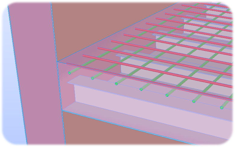
Figure 4.5-a : CAO of a junction between a veil and a floor.
The command lines shown below make it possible to account for the junction between a veil and a floor shown in the figure.
CLIM = AFFE_CHAR_MECA ( … .
LIAISON_MAIL = (
# Floor: Pb1, Junction: Voil1
_F (GROUP_MA_ESCL =( “Pb1 GRaidBord1 “, “Pb1 GToleBasBord1”, ), ),
GROUP_MA_MAIT = “V1 GTole2 “, TYPE_RACCORD =” COQUE “,
TRANSF_GEOM_MAIT =( FV1GTole2DX, FV1GTole2DY,, FV1GTole2DZ ),
DISTANCE_ALARME = 1.50e-01, DISTANCE_MAX = 1.50e-01, ),
_F (GROUP_MA_ESCL = “Pb1 NNp1Bord1 “, GROUP_MA_MAIT = “V1 GTole2”,
TYPE_RACCORD = “COQUE”,
TRANSF_GEOM_MAIT =( FV1GTole2DX, FV1GTole2DY,, FV1GTole2DZ ),
TRANSF_GEOM_ESCL =( FPb1NNp1DX, FPb1NNp1DY,, FPb1NNp1DZ ),
DISTANCE_ALARME = 1.50e-01, DISTANCE_MAX = 1.50e-01, ),
),
)
With:
“V1 GTole2 “: one of the sheets in the veil.
“Pb1 GRaidBord1 “, “Pb1 GToleBasBord1”: the edge of the stiffeners and the edge of the lower sheet of the floor.
“Pb1 NNp1Bord1 “: the edge of the reinforcing sheet.
FV1GTole2DX, FV1GTole2DY, FV1GTole2DZ: the functions that describe the eccentricity of the sheet metal of the veil. The values are those given in the operator AFFE_CARA_ELEM [AFFE_CARA_ELEM] with the keyword EXCENTREMENTpour the sheets of the veil.
FPb1NNp1DX, FPb1NNp1DY, FPb1NNp1DZ: the functions that describe the eccentricity of the reinforcing sheet. The values are those given in the operator AFFE_CARA_ELEM [AFFE_CARA_ELEM] under the keyword EXCENTREMENTpour reinforcement grids.
The figure shows the mesh corresponding to CAO in the figure. The 1/2 thickness of the veil is taken into account when writing the eccentric connections.
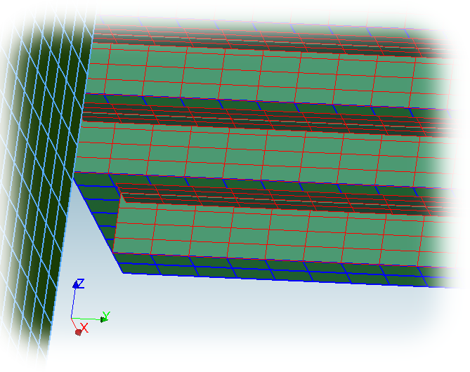
Figure 4.5-b : Mesh of the junction between the veil and the floor, corresponding to CAO shown in figure.