2. Modeling of structural elements#
The finite elements proposed in the following chapters, for the modeling of SCS, allow analyses to be carried out in linear and non-linear, in static, in dynamics, in spectral. These finite elements associated with the laws of behavior (Cf. § 3) also give access to generalized efforts (forces, moments) but also to more local information such as the distribution of stresses and deformations, as well as to criteria ELS and ELU.
The approach adopted is to use the capabilities of the code to model the various components of the structure for both linear and non-linear studies. This will make it possible to keep the same modeling regardless of the type of study and therefore to avoid redoing geometry, meshing, or data. The choice between linear and non-linear will only be based on the type of behavior that will be assigned to the materials.
2.1. Assumption of perfect adherence#
One of the important assumptions in reinforced concrete design [Eurocode2] [BAEL83] is the adhesion between steel and concrete. In the modeling of SCS this hypothesis is also made. This is reflected in the choice of the various finite elements and their assembly, which will be implemented during the studies. The interface between steel and concrete will therefore not be modelled and the adhesion hypothesis will be ensured by the continuity of deformations between the two materials.
2.2. Modeling columns and beams#
Beam and column structural elements are currently not considered in construction SCS. Code_aster makes it possible to model these elements. This § will be completed if required.
2.3. Sail modeling#
The figure shows a CAO of a SCS sail element, shown in the photo.
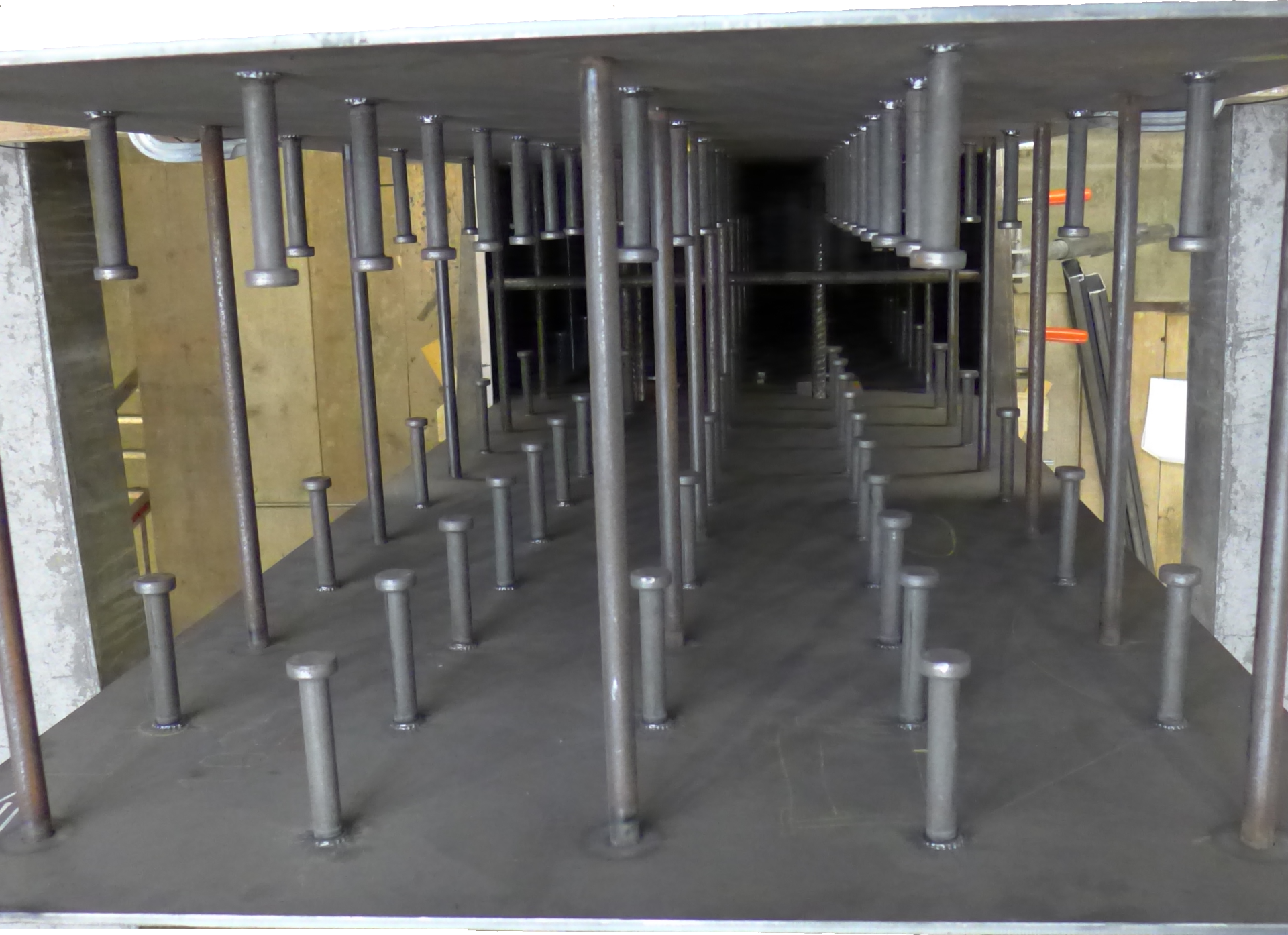
Figure 2.3-a : Sail section in SCS (prgm Science).
To carry out structural analyses, it is necessary to simplify the modeling while making sure to respect the “functioning” of the panel.
The studs ensure the adhesion between steel and concrete. The tie rods prevent the sheets from moving apart while ensuring adhesion between the steel and the concrete, they also take up shear forces.
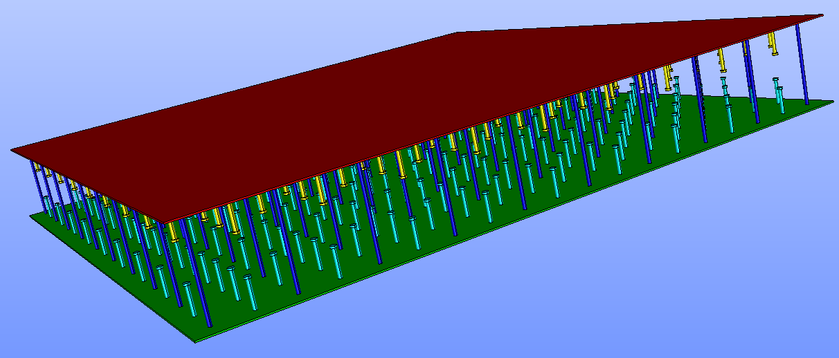
Figure 2.3-b : Geometry of a veil in SCS, under salome_meca.
It is also noted that the two sheets are distant from the mean plane of the web and it is necessary to take this distance into account (noted eccentrically in the rest of the document), as would be done conventionally for sheets of reinforcement.
From the point of view of a finite element approach, the calculation models for SCS walls will be based on plate elements. The elements recommended for studies with code_aster are DKT. They are multi-layered elements, with 3 integration points per layer, which can account for an eccentricity. This choice is guided by the fact that these elements are the only ones compatible, from the point of view of kinematics and the availability of the laws of behavior of concrete, steel plates and reinforcements.
In addition, the kinematics of the dkt plate elements ensures both the adhesion between steel and concrete as well as the non-spacing of the sheets. Therefore, it is not necessary to model studs or ties, the condition of adhesion between the sheets and the concrete being ensured by kinematics.
Note: What about the elements of type DSTou COQUE_3D:
• For the elements*DST*, the theory associated with taking into account transverse shear, is*not compatible with non-linear behaviors (documents code_aster* U3.12.01*,* R3.12.01*,* R3.07.03*) .*
• For the*shell_3D* elements, their kinematics are*not compatible with the elements which*vo*nt*use to model reinforcement*or sheets that require an eccentricity to be taken into account* (documents code_aster*U3.12.04*, U3.12.03) ) .
The use of non-linear behavior requires some precautions for use that can be found in the documentation « [U2.03.07]: Overview of the tools available for carrying out concrete civil engineering structure calculations [U2.03.07] ».
The meshing of this type of structural element therefore becomes very simple, it is only necessary to mesh its average surface, figure.
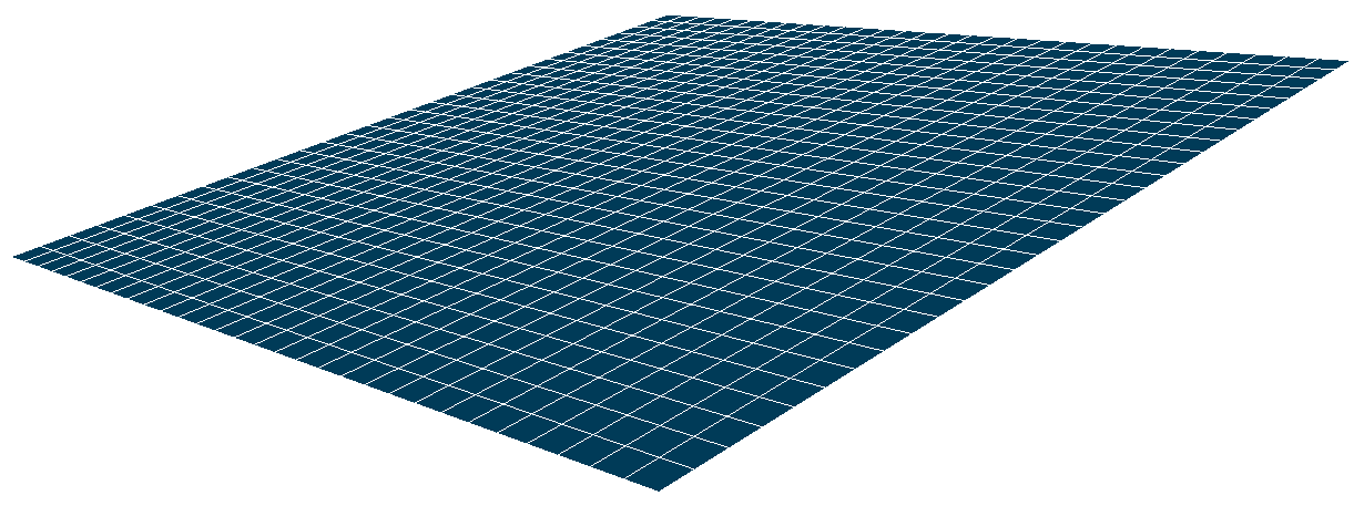
Figure 2.3-c*: Meshing the average area of a veil SCS.*
Information not carried by the mesh (thicknesses, number of layers, position of the sheets, nature of the materials) must be given in the code_aster command file. If the user wishes to modify any of this information, it is not necessary to redo the mesh, simply intervene in the AFFE_CARA_ELEM command which groups this information together.
For linear elastic analyses, the number of layers of the elements modeling concrete has no influence on the values of stresses, deformations, or generalized forces. On the other hand, for non-linear analyses (zero resistance of concrete under tension) the number of layers has an influence on the precision of the position of the neutral axis and therefore on the calculation of stresses and generalized forces [U2.02.01].
The number of layers for modeling concrete can, for example, be guided by the size of the aggregate and by the fact that the law of behavior locally homogenizes the behavior of the concrete material. DKTs have 3 integration points per layer (code_aster document R3.07.03, §4.9). The number of layers recommended to model a thickness of concrete “ep” is:
: label: EQ-None
{N} _ {mathit {layer}} =frac {mathit {ep}} {(3ast {D} _ {mathit {granulate}}})}
The number of layers for modeling concrete can, for example, be guided by the precision you want to have on the position of the neutral axis in the section. In the case of modeling with 7 layers for a 50cm slab, the precision on its position is of the order of \(0.7{D}_{\mathit{granulat}}\).
With the rule set out above, the analyses carried out at ELU on a wall and on a floor under simple bending, compared to a regulatory reinforced concrete calculation (type BAEL, EUROCODE), present a difference that remains less than 3% on the maximum stress in steel and in concrete [PRD_Tristan_BERNELLE].
Note: When a loading is gradually applied to a structure and material non-linearities appear, they also appear gradually: concrete cracks progressively, steels gradually plasticize. This means that the neutral axis is moving. Taking this effect into account is necessary and is possible with multi-layered DKT elements. On the other hand, the use of non-linear behavior requires some precautions for use that can be found in the documentation « [U2.03.07]: Overview of the tools available for carrying out concrete civil engineering structure calculations [U2.03.07] ».
2.4. Modeling floors with stiffeners#
The figure shows a schematic diagram of the floor shown in the photo. The role of the studs, which are welded to the lower sheet, is to ensure the connection between the concrete and the sheet. As with walls, the studs that ensure the adhesion between steel and concrete will not be modeled, the connection is said to be complete.
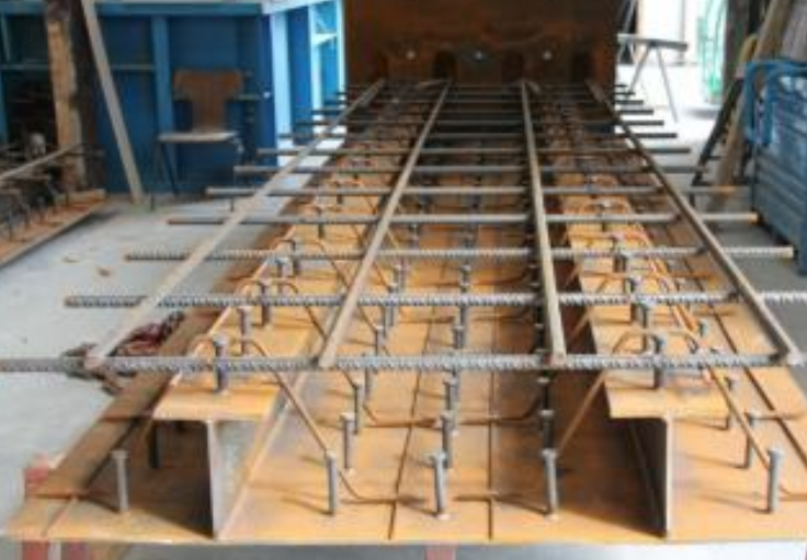
Figure 2.4-a : Principle of a SCS floor, model SAM.
Finite element modeling of floors will be based on plate elements, as for walls. The elements DKTqui are used to model the lower sheet and the concrete will ensure the perfect adhesion condition, cf.§ 2.5.
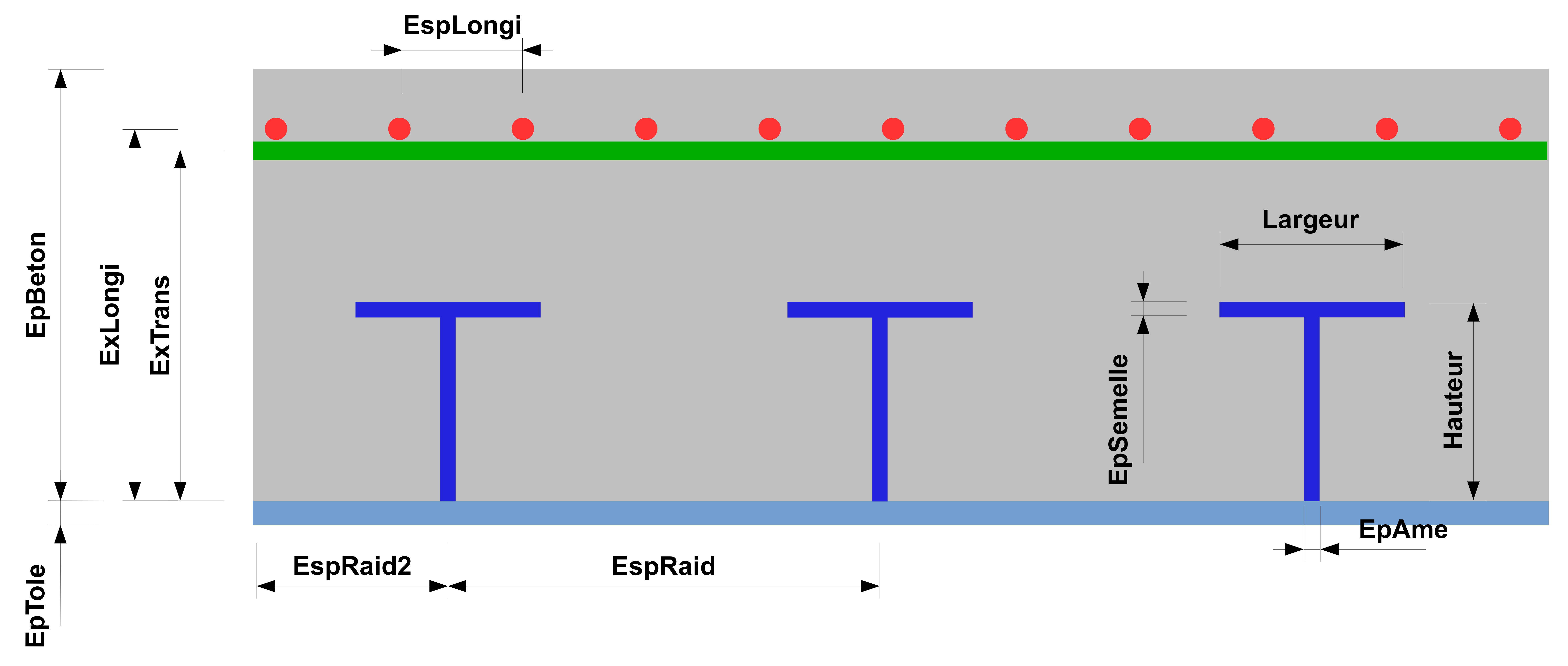
Figure 2.4-b: Schematic diagram of a floor with a stiffener.
The figure shows a CAO used to create the mesh.
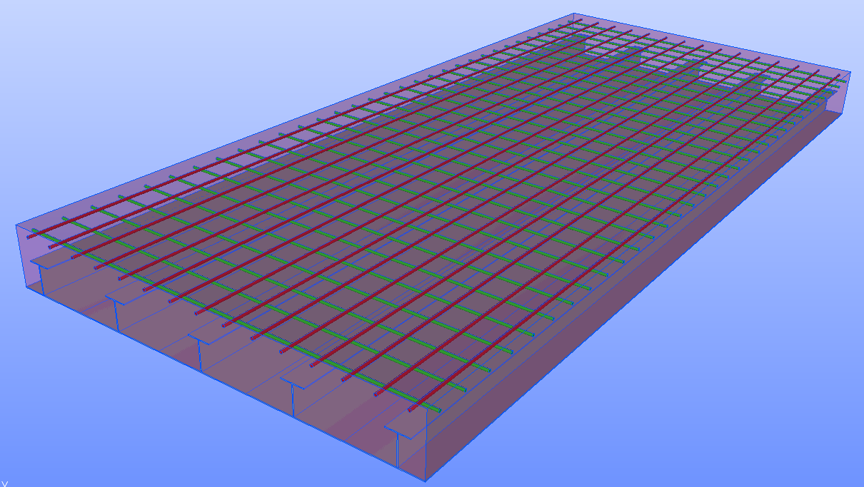
Figure 2.4-c: CAO of a p*plancher*, made*under Salome_meca.*
The steel sheets will be modelled by elements of the grid_excentre type, which are classically used for civil engineering studies. They are 1-layer elements with only one integration point in the layer.
The figure shows the view of the mesh used to model a floor with a stiffener. To impose the same kinematics between sheet metal, concrete and reinforcement layers, it is necessary for the finite elements to share the same degrees of freedom. To do this, the concrete meshes and the sheets will come from the duplication of the meshes of the sheet metal (Cf. appendice§ 7.1). This operation can be performed either in the Salome_Meca Mesh module, or in the code_aster command file. The eccentricity of the sheets will be specified in the command file [AFFE_CARA_ELEM] to take into account their positions.
The design of this floor also involves stiffeners that are welded to the lower sheet. To have a description as close as possible to this design, it is necessary to take into account this welded connection (Cf § 4.2). Two solutions are possible:
the stiffeners are meshed by imposing conditions of compatibility of their mesh with that of the sheet.
the stiffeners will not be meshed with a mesh size that coincides with that of the sheet. In this case, the description of this link can be done with the keyword LIAISON_MAIL from the AFFE_CHAR_MECA [AFFE_CHAR_MECA] U4.44.01 command.
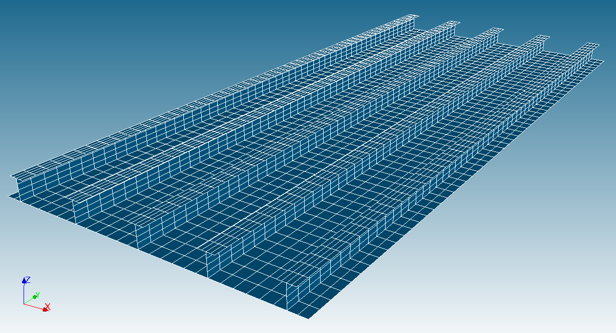
Figure 2.4-d: Floor mesh*.*
Information not carried by the mesh (thicknesses of the sheets, of concrete, of the number of layers, of the position of the sheets, of the nature of the materials,…) must be given in the code_aster command file. If the user wishes to modify any of this information, there is no need to redo the mesh, simply modify the characteristics in command AFFE_CARA_ELEM.
2.5. Eccentricity of plate elements#
Whether for the modeling of walls or floors with finite elements of plate DKTla, taking into account the position of the components (reinforcements, sheets,…) in relation to each other is necessary. This position is defined by giving the eccentricity in relation to its surface mesh. It is this approach that is used in code_aster to model reinforcement layers when studying reinforced concrete structures (code_aster documents U2.03.07, U3.12.04).
Finite plate elements DKT (concrete, sheet metal, stiffener) and GRILLE_EXCENTRE (reinforcements) make it possible to account for this eccentricity.
The principle of implementation in code_aster is the same for DKTet and GRILLE_EXCENTRE:
The supports are meshed by surface elements.
It is necessary to orient the normal to the surface. The orientation can be defined either when creating the mesh, or in the code_aster command file. This orientation is used for several purposes:
◦ when loading pressure, it is necessary to know the normal (documents code_aster [AFFE_CHAR_MECA] U4.44.01).
◦ when the elements have several layers, this is used to know the number of the layer in order to then be able to extract the results (documents code_aster [AFFE_CARA_ELEM] U4.42.01, U4.42.01, U2.02.01).
◦ define eccentricity It is positive in the normal sense (code_aster documents [AFFE_CARA_ELEM] U4.42.01, U2.02.01).
For example, for a veil SCS, if the mesh represents the mean area of the veil, one of the sheets will have a positive eccentricity and the other a negative eccentricity. In this case, the concrete will have zero eccentricity.
Excerpt of commands for a veil:
CareLem = AFFE_CARA_ELEM (
MODELE = Model,
COQUE = (
# Sail: V1
_F (GROUP_MA =( “V1 GBeton “, )) ,, EPAIS = 4.840e-01, COQUE_NCOU = 7, )) **,
_F (GROUP_MA =( “V1 GTole1 “, )) ,) , EPAIS =**8.000e-03,** EXCENTREMENT =**-2.460e-01,**, )) **,
_F (GROUP_MA =( “V1 GTole2 “, )) ,) , EPAIS =**8.000e-03,** EXCENTREMENT =**2.460e-01,**, )) **,
),
)
For example, for a SCS floor, the mesh represents the average area of the lower sheet, so the concrete and the reinforcement sheets will have an eccentricity, whose sign will be defined by the orientation of the normal.
Excerpt of orders for a floor:
CareLem = AFFE_CARA_ELEM (
MODELE = Model,
COQUE = (
# Floor: Pb1
_F (GROUP_MA =( “Pb1 GToleBasSurf “, )) ), EPAIS = 8.00e-03, VECTEUR =( 0.0, 1.0, 0.0 )) )) **,
_F (GROUP_MA =( “Pb1 GBeton “, )) ), EPAIS = 5.00e-01, VECTEUR =( 0.0, 1.0, 0.0 ),
EXCENTREMENT = 2.540e-01, COQUE_NCOU = 7, ),
),
GRILLE = (
# Floor: Pb1, Tablecloth: Np1. 15φ25/3.60m
_F (GROUP_MA =( “Pb1 NNp1 “, )) ,) , SECTION =**2.0453077172e-03,** VECT_1 =( 0.0, 1.0, 0.0) **,
EXCENTREMENT = 4.4550e-01, ),
# Floor: Pa1, Table: Np2. 32φ25/8.00m
_F (GROUP_MA =( “Pb1 NNp2 “, )) ,) , SECTION =**1.9634954085e-03,** VECT_1 =( 1.0, 0.0, 0.0) **,
EXCENTREMENT = 4.2050e-01, ),
),
)
For the definition of eccentric elements, other choices are possible:
For walls, if the position of the surface mesh corresponds to one of the sheets, the other sheet will be eccentric by the thickness of the wall and the concrete offset by its half-thickness.
For floors, if the position of the mesh corresponds to the mean plane of the concrete, the lower sheet will be eccentric as well as the reinforcement sheets, with different signs.
If the position of the mesh does not correspond to any mean plane of one of the elements, all of them must therefore be offset.
During this phase, the definition of the normal to the mesh surface is necessary in order to properly offset the elements from each other.