7. Appendix#
7.1. Duplication of meshes#
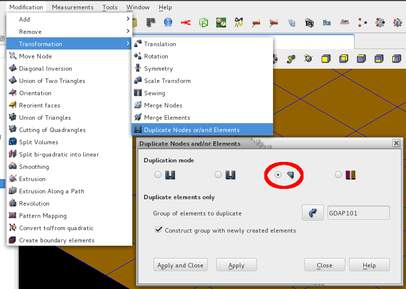
The duplication of the meshes can be done either in the Mesh module or with code_aster commands.
In the Salomé_Méca Mesh module:
In the code_aster command file:
MAILL2 = CREA_MAILLAGE (MAILLAGE = MAILL1,
CREA_MAILLE =_F ( NOM = “GDAP105”, “, GROUP_MA =**” GDAP101 “,** PREF_MAILLE =**” B “,**) )
)
7.2. Example of a connection between sail and floor#
Modeling the connection between a wall and a floor using the approach below is not recommended.
The figures show a possible modeling of the connection, carried out using finite plate elements. The figures show CAO corresponding to this modeling, by showing the thicknesses of the various elements.
Besides the fact that the floor is connected to the middle plane of the veil, the eccentricity of the reinforcing layers is also not taken into account. To better model this link it would be necessary to:
that the floor is correctly positioned, and therefore tangential to one of the sheets of the veil.
that the distance (1/2 thickness of the veil) between the middle plane of the veil and the floor is correctly taken into account. The connection between the wall and the lower sheet of the floor, the stiffeners as well as the reinforcement sheets must take into account the real distances. Not taking into account the position of the elements in relation to each other leads to an « unrealistic » effort twister.
that the eccentricity of the reinforcing layers of the floor be taken into account. The connection must take into account the area where the reinforcements are anchored in the web, taking into account their real position.
The 3 previous points are « corrected » when using « eccentric connections », cf. § 4.3.
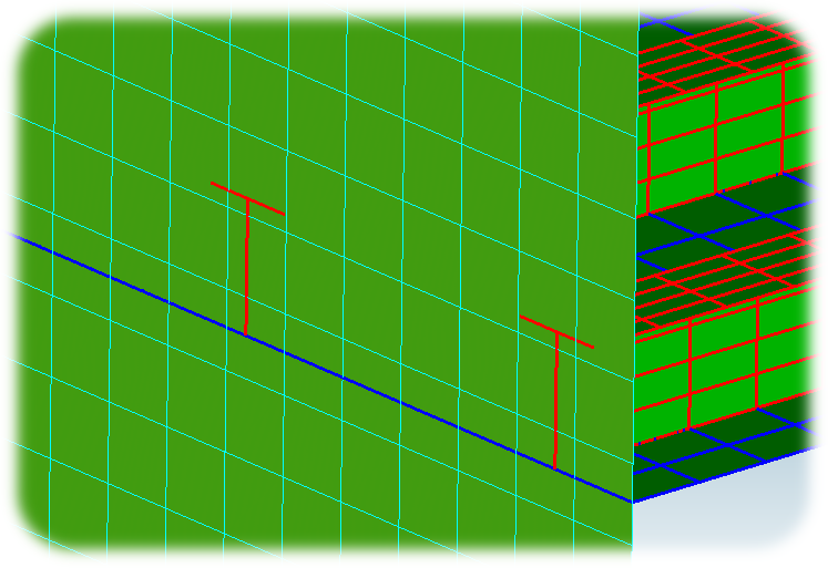
Figure 7.2-a |
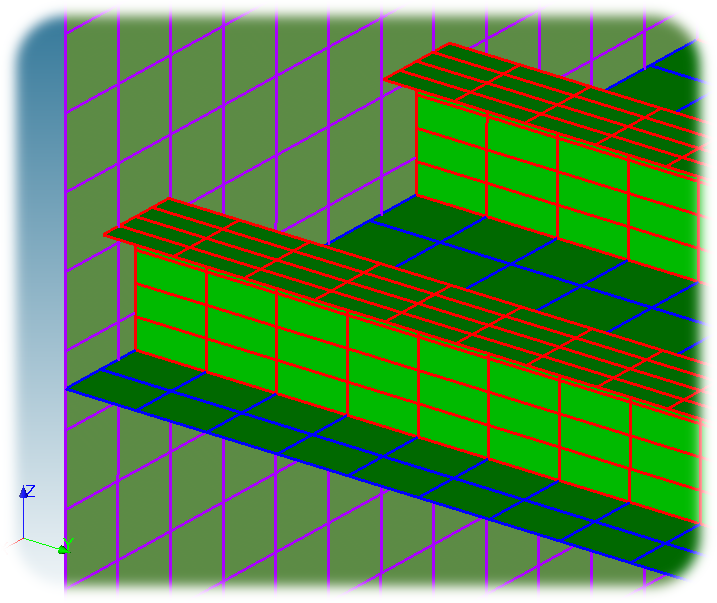
Figure 7.2-b |
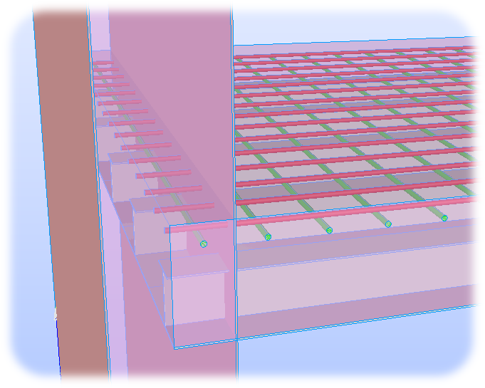
Figure 7.2-c |
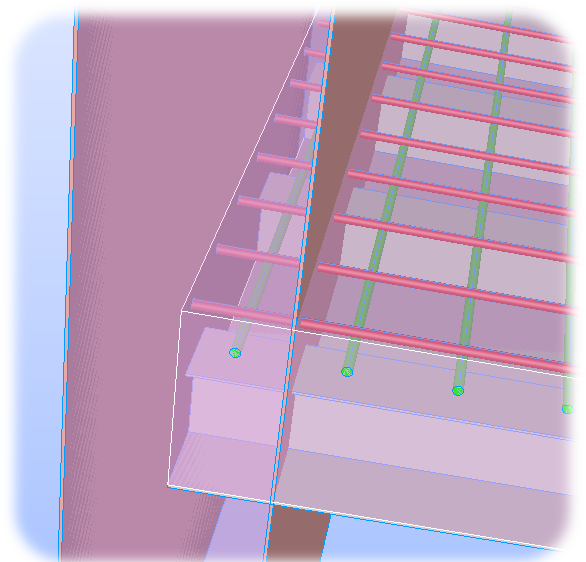
Figure 7.2-d |
7.3. Eccentric connection: test case zzzz419#
Commands from test case ZZZZ419 [V1.01.419] from the code_aster verification database.
# Mesh: floor at 2.0 m. Will be offset by 0.50m ==> in the end 2.5m
mesh20 = LIRE_MAILLAGE ( UNITE =20, FORMAT =” MED “, )) **
# Mesh: floor at 2.5 m
mesh25 = LIRE_MAILLAGE ( UNITE =25, FORMAT =” MED “, )) **
model20 = AFFE_MODELE (
MAILLAGE = mesh20,
AFFE =_F (MODELISATION =( “DKT”, )) ,) , PHENOMENE =**”MECANIQUE”,** TOUT =**”OUI”, **)
)
model25 = AFFE_MODELE (
MAILLAGE = mesh25,
AFFE =_F (MODELISATION =( “DKT”, )) ,) , PHENOMENE =**”MECANIQUE”,** TOUT =**”OUI”, **)
)
# Functions for moving during the pairing phase*
TrfXe = FORMULE (NOM_PARA = [“X”,], VALE = “X”, )) **
TrfyE = FORMULE (NOM_PARA = [“Y”,], VALE = “Y”, )) **
Trfze = FORMULE (NOM_PARA = [“Z”,], VALE = “Z+0.50”, )) **
load20 = AFFE_CHAR_MECA (
MODELE = model20,
LIAISON_MAIL =(
_F (GROUP_MA_ESCL =( “MGBordPlaGau”, )) ,, GROUP_MA_MAIT =( “MGFaceMur”, )) **,
TYPE_RACCORD = “COQUE”, TRANSF_GEOM_ESCL = **** (TrfXe, TrfyE, TrfZe) **,
),
),
)
load25 = AFFE_CHAR_MECA (
MODELE = model25,
LIAISON_MAIL =(
_F (GROUP_MA_ESCL =( “MGBordPlaGau”, )) ,, GROUP_MA_MAIT =( “MGFaceMur”, )) **,
TYPE_RACCORD = “COQUE”,
),
),
)