1. Introduction#
The objective of this document is to define the various elements necessary to model and study the behavior of « SteelConcrete Structure: SCS » during linear and non-linear analyses, at the scale of a building. Therefore, models implementing approaches with finite volume elements are not in the scope of this document.
This document outlines the following points:
finite elements to model walls, floors,
the laws of behavior for steel and concrete materials,
the recommendations concerning the use of the 2 previous points, taking into account the necessary balance between the fineness of the results, the time to analyze the results, the time to calculate the data, the time to enter the data.
modeling the connections between the various structural elements.
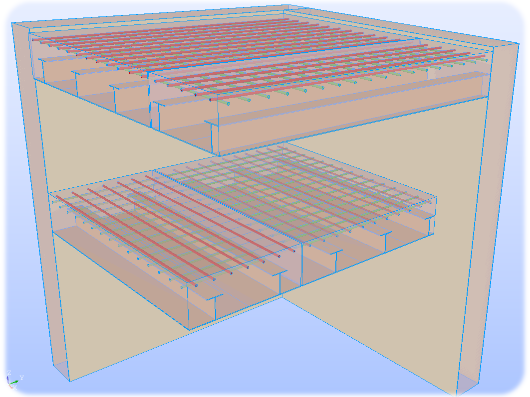
Figure 1-a : Model CAO, from model SAM [D305918007339] [CQN3725NWD004BPE_B] [CQN3725PDP035BPE_B].
1.1. The analyses to be carried out#
The types of studies and loads envisaged are [6125-1715-2018-03864-FR] [6125-1723-2019-02944-EN]:
Statics: forces, pressures, displacements, taking into account the effects of temperature, hydration, drying, corrosion,…
Dynamics: transitory and harmonic on a modal and physical basis, by spectral response,
Post-processing of the results: ELS, ELU, stresses, deformations, deformations, generalized efforts, movements, reactions to supports, vibration modes, floor spectra,…
1.2. Linear vs non-linear approaches#
One of the objectives of the recommendations is to respond to both linear and non-linear approaches with a finite element code while minimizing engineering time to move from one analysis to another.
To meet this objective:
The non-linear will only be driven by the behavior of the « steel » and/or « concrete » materials.
The CAOet meshing will be common to both types of analyses.
Note: The use of non-linear behavior requires some precautions for use that can be found in the documentation « [U2.03.07]: Overview of the tools available to perform concrete Civil Engineering structural calculations [U2.03.07] » .
1.2.1. Linear analyses#
During a linear analysis, all materials must have a linear behavior regardless of the loads imposed.
For example, concrete that cracks during loading does not have a linear behavior. It is therefore not possible, in the general case, to perform a linear analysis when one wishes to take account of concrete cracking.
Note: Regulatory approaches in border states* ELS and ELU consider that cracked concrete does not resist traction, in this case its behavior is therefore non-linear.
1.2.2. Equivalent linear analyses#
When you want to take into account the cracking of concrete or the plasticization of steels and still to do linear analyses, it is possible to carry out « equivalent linear » analyses.
To conduct this type of analysis, it is necessary to make assumptions about the behavior of structural elements, for example about how concrete will crack (position of the neutral axis,…).
The first phase is to calculate the mechanical characteristics by assuming a « limiting » behavior of the materials (in terms of stresses and/or deformations), using for example the diagram of the 3 pivots. From this, the mechanical characteristics are calculated.
This approach is described in the documents resulting from the Science project [D7.9] [D305917010338]. The proposed models are based on a classical reinforced concrete approach that is adapted to SCS, taking into account the presence of sheet metal plates (for walls and floors) and stiffeners (for floors). The modeler knowing the geometry, the materials as well as their limit state can calculate the homogenized properties (thickness, section, inertia,…). Document D7.9 [D7.9] presents the methodology to be used to perform a homogenization calculation of mechanical characteristics based on geometry and materials.
The second phase is to enter the homogenized characteristics into a calculation code in order to then perform the linear analysis. Once the calculations have been carried out, if we want to know the stresses and deformations, it is necessary to apply the methodology presented in §5 « Conversion of shell results to plate stresses » in D7.9.
The difficulties of this approach are of several types:
When the stresses are biaxial and the elements have asymmetries, it is necessary to determine the homogenized characteristics in the different directions.
It is necessary to verify that the results obtained are in accordance with the assumptions made during the homogenization phase for all structural elements and for all loads.
The homogenization phase depends on both geometry and materials. A change in sheet thickness, concrete class, section or position of a reinforcement sheet will require this homogenization phase to be repeated.
1.2.3. Linear and non-linear analyses with a finite element code#
The approach proposed in the rest of the document allows linear or non-linear analyses to be carried out by only changing the behavior of the materials.
The data required to carry out this process is identical to that of § 1.2.2. On the other hand, it is essential that the laws of behavior be able to describe non-linear behaviors, for example plasticity for steels and cracking for concrete (Cf. § 3 on the laws of behavior).
In this approach:
The finite element calculation code makes balance calculations in the sections of structural elements according to the evolution of the nonlinearities of the materials.
The calculation code allows access to variables of interest such as constraints, deformations, displacements,…
The position of the elements (sheets, concrete, reinforcement sheets) will be determined by the mesh and by the characteristics given in the command file.
A change in sheet thickness, concrete class, section or position of a reinforcement sheet will require changing the appropriate parameters in the command file but without redoing the meshing.
Note: The use of non-linear behavior requires some precautions for use that can be found in the documentation « [U2.03.07]: Overview of the tools available to perform concrete civil engineering structure calculations [U2.03.07] ».