4. B modeling#
4.1. Characteristics of modeling#
This modeling is strictly identical to the previous one, except for the elements used, which are quadratic.
4.2. Characteristics of the mesh#
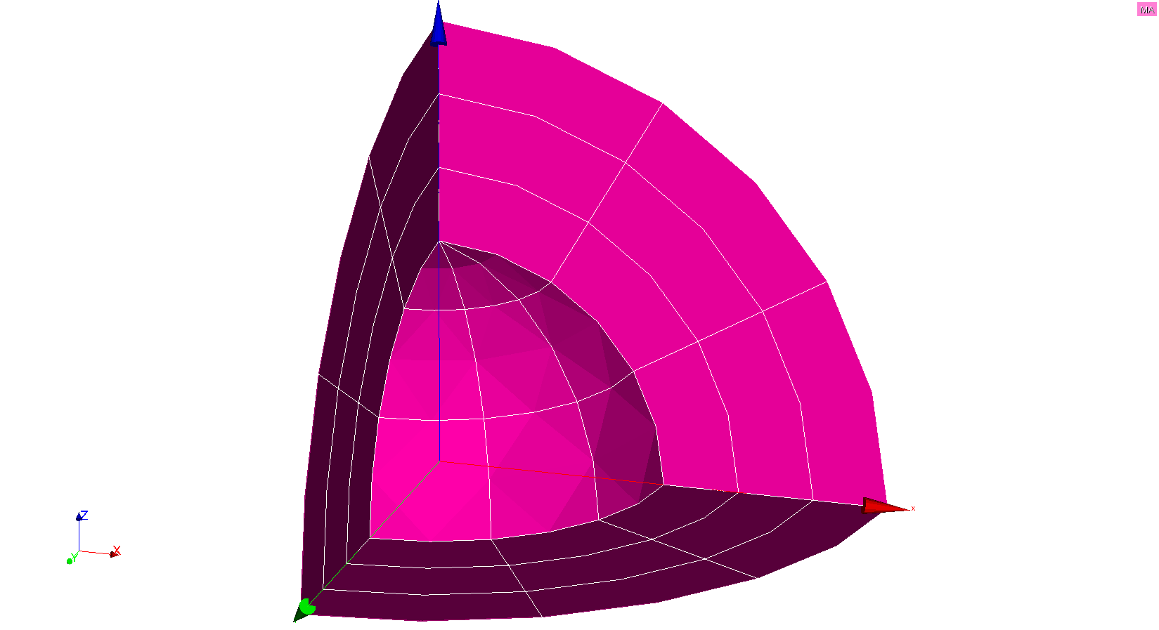
The shell on which the modeling is performed is divided into 18 HEXA20 and 9 PENTA15. The interface is not meshed and cuts through the shell in its thickness. The mesh is shown in Figure.
Figure 4.2-a : Quadratic 3D mesh
4.3. Tested sizes and results#
The results are obtained with*Code_Aster* (resolution with STAT_NON_LINE). We test the radial displacements \({u}_{r}\) on the lips of the crack. For each crack, we test the MIN and the MAX of these two sizes for all the nodes in the crack. The results obtained are summarised in the table below.
Quantities tested |
Reference type |
Analytical values |
Tolerance (%) |
|
DR (int) MIN |
“ANALYTIQUE” |
-0.0001142742582 |
“” |
|
DR (int) MAX |
“ANALYTIQUE” |
-0.0001142742582 |
“” |
|
DR (ext) MIN |
“ANALYTIQUE” |
6.173526141E-05 |
“” |
|
DR (ext) MAX |
“ANALYTIQUE” |
6.173526141E-05 |
“” |
The radial displacement \({u}_{r}\) and the deformation are shown in Figure. A clear discontinuity of the movements and the spherical symmetry of the fields are observed.
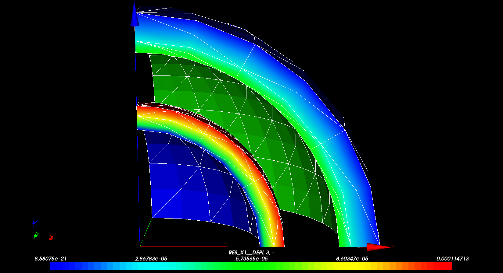
Figure 4.3-a : Radial displacement field
With the same number of cells as in the previous modeling, we obtain results that are much more precise (we gain a factor of 10 in precision on the movements). These two models once again illustrate the considerable contribution of quadratic elements compared to linear elements. The results obtained in this last modeling are completely satisfactory, especially in view of the low number of cells used and the curvature of the LSN.