3. Modeling A#
3.1. Characteristics of modeling#
It is a 3D model using linear XFEM elements.
3.2. Characteristics of the mesh#
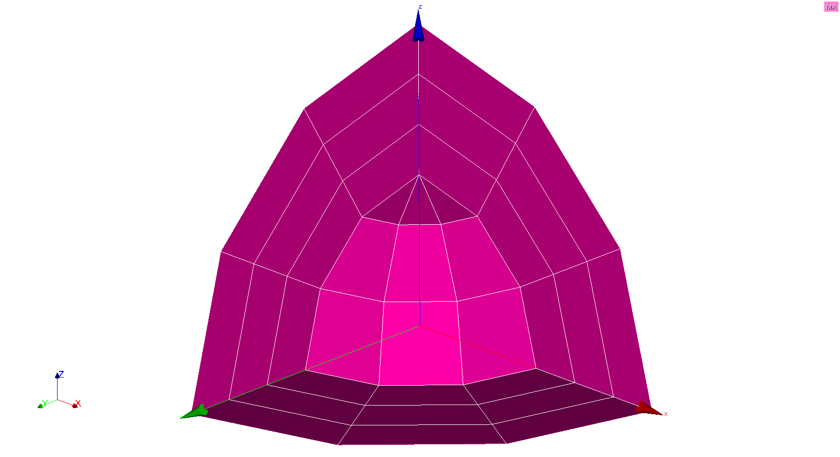
The spherical shell on which the modeling is performed is divided into 18 HEXA8 and 9 PENTA6. The interface is not meshed and cuts through the shell in its thickness. The mesh is shown in Figure.
Figure 3.2-a : Linear 3D mesh
3.3. Tested sizes and results#
The results are obtained with*Code_Aster* (resolution with STAT_NON_LINE). We test the radial displacements \({u}_{r}\) on the lips of the crack. For each crack, we test the MIN and the MAX of these two sizes for all the nodes in the crack. The results obtained are summarised in the table below.
Quantities tested |
Reference type |
Analytical values |
Tolerance (%) |
|
DR (int) MIN |
“ANALYTIQUE” |
-0.0001142742582 |
“” |
|
DR (int) MAX |
“ANALYTIQUE” |
-0.0001142742582 |
“” |
|
DR (ext) MIN |
“ANALYTIQUE” |
6.173526141E-05 |
“” |
|
DR (ext) MAX |
“ANALYTIQUE” |
6.173526141E-05 |
“” |
The radial displacement \({u}_{r}\) and the deformation are shown in Figure. A clear discontinuity of the movements and the spherical symmetry of the fields are observed.
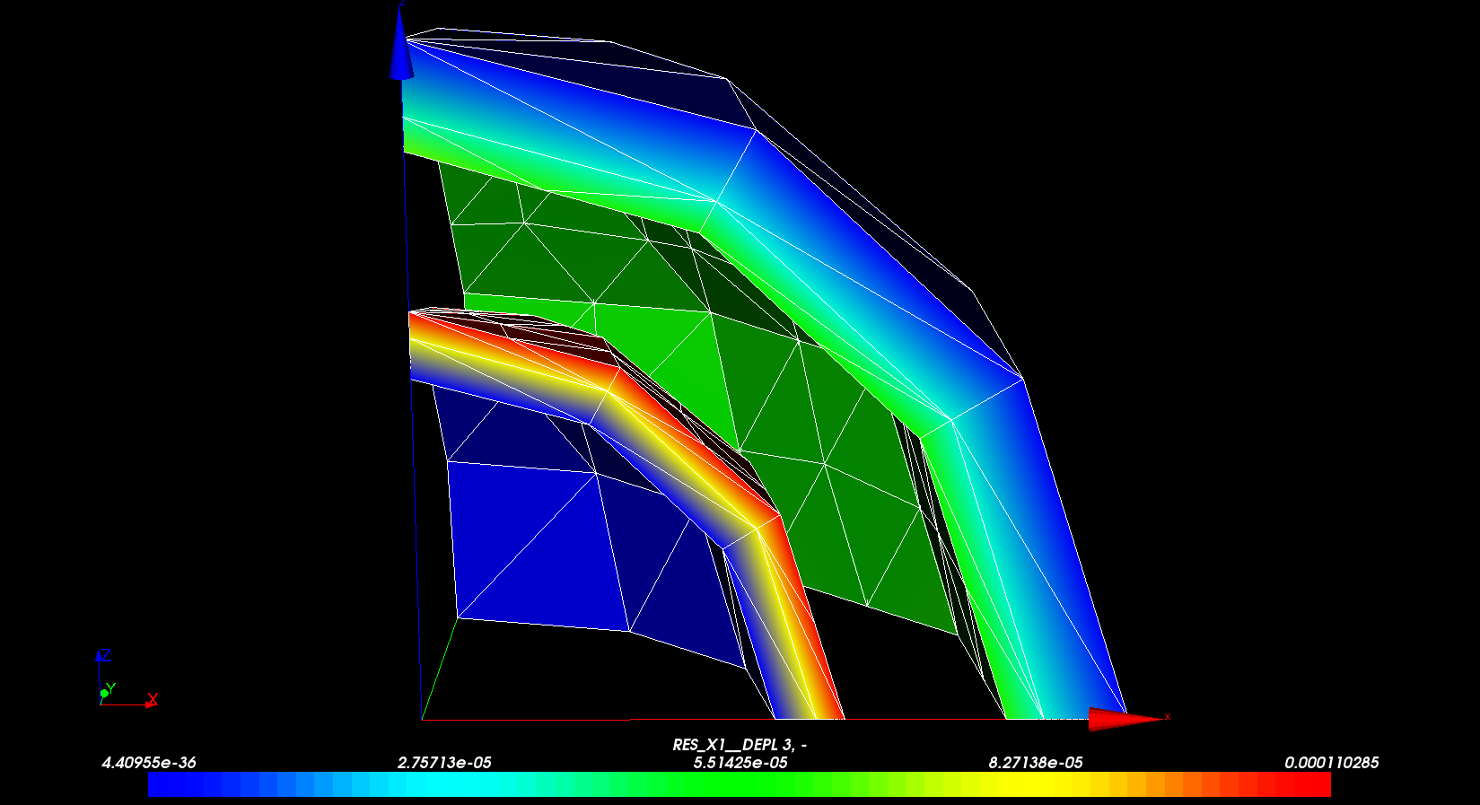
Figure 3.3-a : Radial displacement field
The differences observed with the analytical solution should be put into perspective with the poverty of the mesh used. Only 3 meshes are used in the thickness of the shell and in the longitudinal and southern directions.