5. C modeling#
5.1. Characteristics of modeling#
It is a 3D model using linear XFEM elements. The column on which the modeling is performed is divided into 5 HEXA8. The interface is unmeshed and cuts the column in \(Z={L}_{d}=\frac{2\ast \mathit{LZ}}{5}\). The interface is thus in accordance with the mesh. We have 2 XFEM elements and 3 classic elements.
5.2. Characteristics of the mesh#
The mesh composed of 5 HEXA8 is shown in Figure.
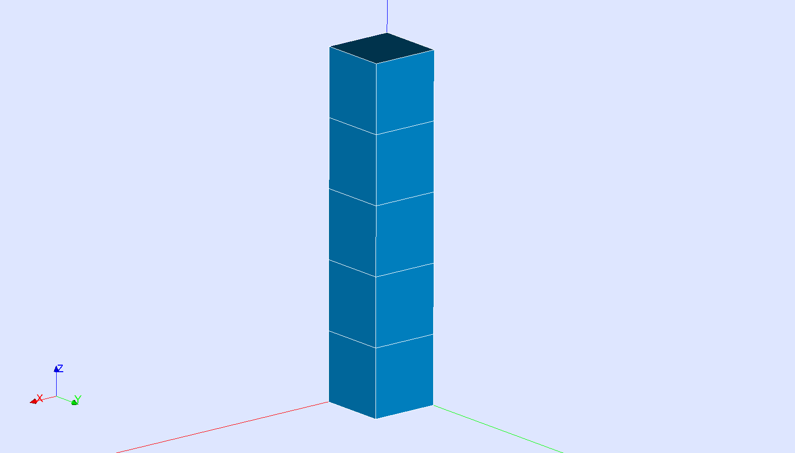
Figure 5.2-a : 2D mesh
5.3. Tested sizes and results#
The results (resolution with STAT_NON_LINE) are summarized in the table below for the \(z\) direction. We test the following \(z\) movement of the interface nodes.
Quantities tested |
Reference type |
Reference value |
Tolerance (%) |
DZ (below) MIN |
“ANALYTIQUE” |
-2.0E-02 |
0.001 |
DZ (above) MAX |
“ANALYTIQUE” |
3.0E-02 |
0.001 |
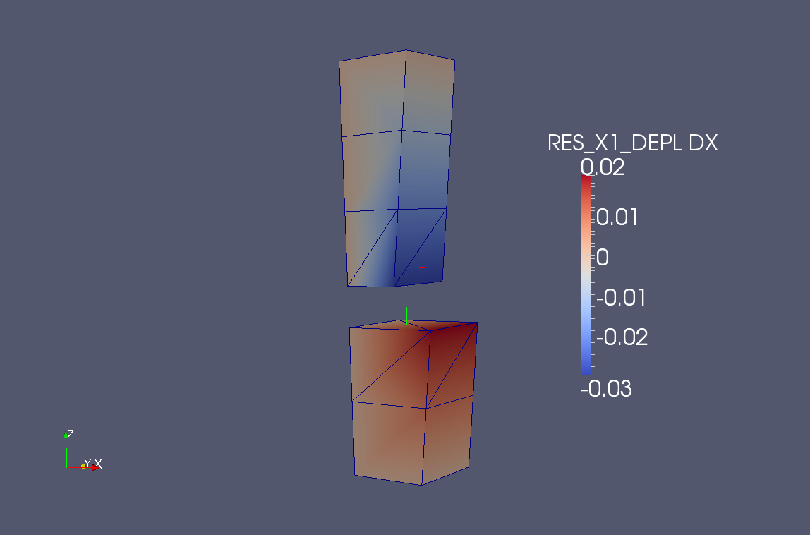
We also test the displacement along \(x\) of two interface nodes located on the face [BCFG] and respectively on the lower and upper lip of the crack.
Quantities tested |
Reference type |
Reference value |
Tolerance (%) |
DX (underside [BCFG]) |
“ANALYTIQUE” |
2.0E-02 |
0.001 |
DX (above face [BCFG]) |
“ANALYTIQUE” |
-3.0E-02 |
0.001 |
The displacement field is presented in the direction \(z\) (Figure) and \(x\) (Figure).
Figure 5.3-a : Field of movement by direction (Oz)
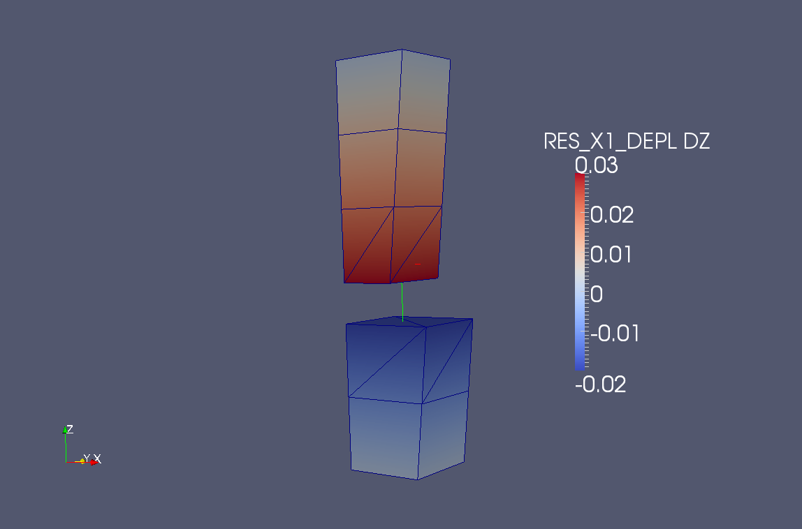
Figure 5.3-b : Field of movement according to direction (Ox)