3. Modeling A#
3.1. Characteristics of modeling#
This is a D_ PLAN modeling using linear XFEM elements.
The interface is unmeshed and cuts off the center element in \(Y={L}_{d}=\frac{13\ast \mathit{LY}}{25}\). So we have 3 XFEM elements and 2 classic elements. As indicated in the Figure, the 3 elements XFEM are subdivided into sub-triangles (to perform the Gauss-Legendre integration on either side of the lips of the interface, but these triangular sub-elements are not mesh elements).
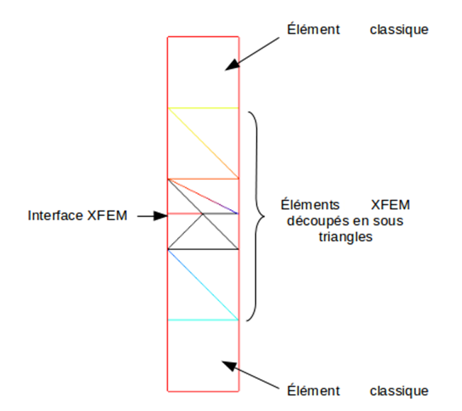
Figure 3.1-a : Characteristics of modelling
3.2. Characteristics of the mesh#
The mesh composed of 5 QUAD4 is shown in Figure.
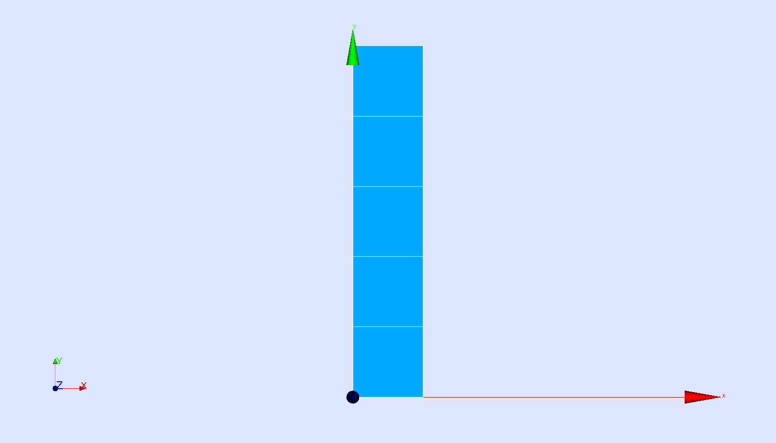
Figure 3.2-a : 2D mesh
3.3. Tested sizes and results#
The results (resolution with STAT_NON_LINE) are summarized in the table below for the \(y\) direction. We are testing the following \(y\) movement of the interface nodes.
Quantities tested |
Reference type |
Reference value |
Tolerance (%) |
DY (below) MIN |
“ANALYTIQUE” |
-2.6E-02 |
0.001 |
DY (above) MAX |
“ANALYTIQUE” |
2.4E-02 |
0.001 |
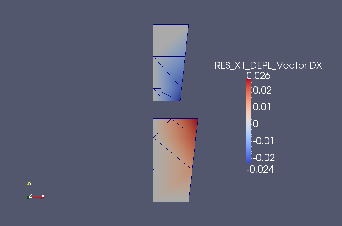
We also test the displacement along \(x\) of the two interface nodes located on the [BC] side and respectively on the lower and upper lip of the crack.
Quantities tested |
Reference type |
Reference value |
Tolerance (%) |
DX (below [BC]) |
“ANALYTIQUE” |
2.6E-02 |
0.001 |
DX (above [BC] side) |
“ANALYTIQUE” |
-2.4E-02 |
0.001 |
The displacement fields are presented in the direction \(y\) (Figure) and \(x\) (Figure).
Figure 3.3-a : Field of movement by direction (Oy)
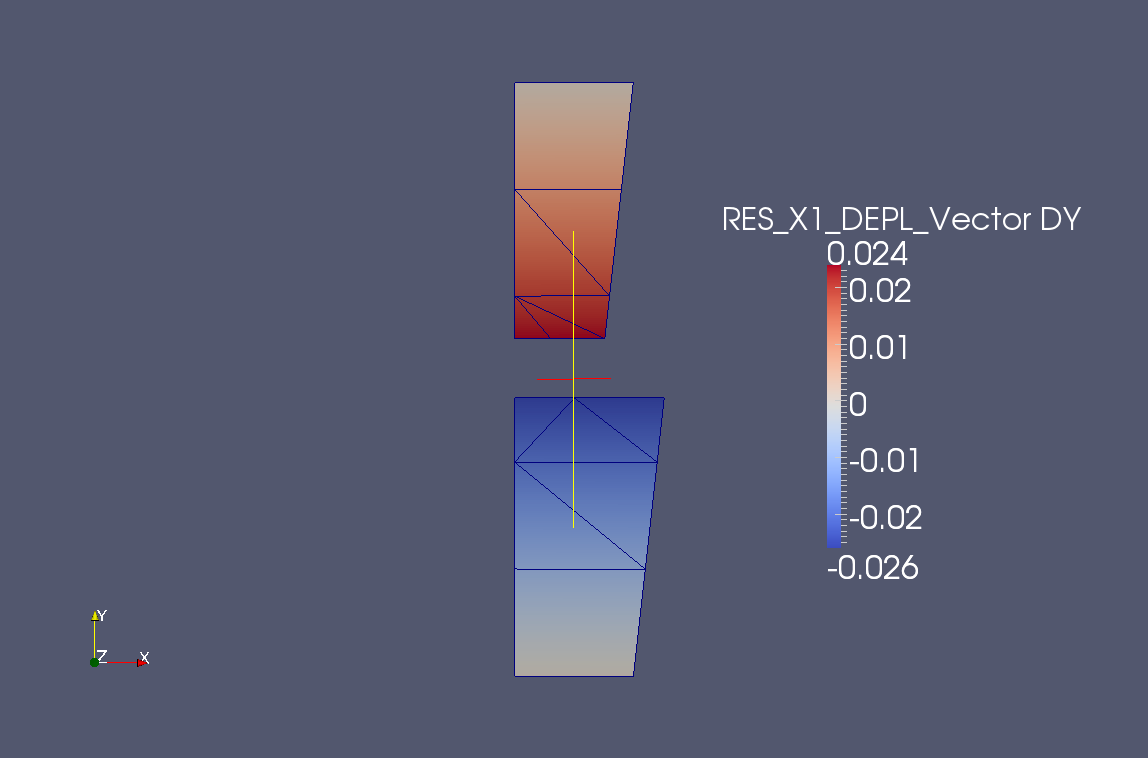
Figure 3.3-b : Field of movement according to direction (Ox)