1. Reference problem#
1.1. 3D geometry#
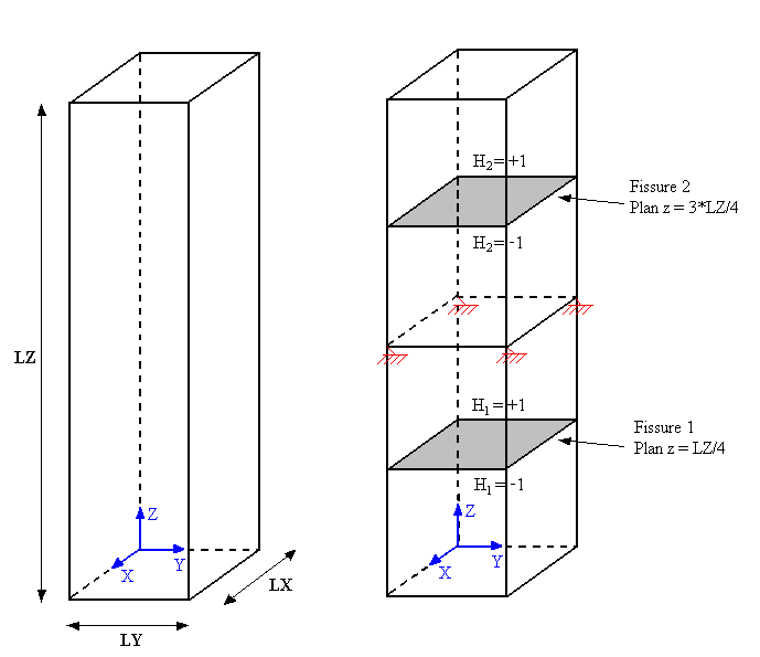
The structure is a straight parallelepiped with a square and healthy base. The dimensions of the bar (see [Figure1.1-1]) are: \(\mathit{LX}\mathrm{=}5m\), \(\mathit{LY}\mathrm{=}5m\) and \(\mathit{LZ}\mathrm{=}50m\). There are no cracks in it.
The interfaces will be introduced by level functions (level sets noted \(\text{LN}\) for normal level set) directly into the command file using the DEFI_FISS_XFEM [U4.82.08] operator. Initially, the interfaces will be horizontal, and each introduced in the middle of the lower and upper blocks in relation to the embedded section (see [Figure1.1-2]). The equations of the level functions for the two horizontal interfaces are therefore as follows:
\(\text{LN1}\mathrm{=}Z\mathrm{-}\text{LZ}\mathrm{/}4\) eq 1.1-1
\(\text{LN2}\mathrm{=}Z\mathrm{-}3\mathrm{\cdot }\text{LZ}\mathrm{/}4\) eq 1.1-2
No tangential level set is necessary since the keyword TYPE_DISCONTINUITE =” INTERFACE “was used, which makes it possible to have a structure completely divided into three parts.
1) 2)
Figure 1.1. Bar geometry and crack positioning
For C modeling, the two interfaces will be inclined undergoing rotations along the \(\mathit{OX}\) axis (see []). On this occasion, we also test the proper functioning of the post-treatment operators in X- FEM who have undergone modifications during the transition to multi-cracking.
1.2. 2D geometry#
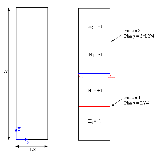
The structure is a healthy rectangle. The dimensions of the bar (see [Figure1.2-1]) are: \(\mathit{LX}\mathrm{=}5m\) and \(\mathit{LY}\mathrm{=}50m\). There are no cracks in it.
The interfaces will be introduced by level sets directly into the command file using the DEFI_FISS_XFEM [U4.82.08] operator. By analogy with case \(\mathrm{3D}\), the interfaces are present in the middle of the two parts of the plate, separated by the embedding line (see Figure 1.2-a). The corresponding equations of the level functions are:
\(\text{LN1}=\text{Y}-\text{LY}/4\) eq 1.2-1
\(\text{LN2}=Y-3\cdot \text{LY}/4\) eq 1.2-3
No tangential level set is necessary since the keyword TYPE_DISCONTINUITE =” INTERFACE “was used, which makes it possible to have a structure completely divided into three parts.
1) 2)
Figure 1.2. Plate geometry and crack location
1.3. Material properties#
Young’s module: \(E\mathrm{=}100\mathit{MPa}\)
Poisson’s ratio: \(\nu \mathrm{=}0.0\)
1.4. Boundary conditions and loads#
The nodes on the median surface of the bar are embedded (see [Figure 1.1-2] and [Figure 1.2-2]) while displacements are imposed on those on the lower and upper surfaces. We want to show firstly the possibility of separating a structure into 3 parts following the introduction of two interfaces (the imposed movements will open the interfaces) and secondly we will prove that the contact on the lips of two interfaces is taken into account (the imposed movements will close the interfaces).