2. Modeling A: Openable horizontal interfaces#
2.1. Characteristics of the mesh#
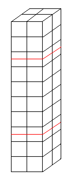
Figure 2.1-1: The A modeling mesh
We discretize the structure using finite elements HEXA8. According to the three directions of the chosen reference system, we have \(2\mathrm{\times }2\mathrm{\times }10\) elements so a total of 40 finite elements (see [])
The number of stages of elements in the direction \(Z\) was chosen to avoid the enrichment of the same element by the two interfaces. In fact, in the implementation of multi-cracking (see manual), we avoid approaching two cracks with less than 4 healthy elements in order to avoid conflicts when managing enriched degrees of freedom.
Thus, by choosing 10 floors, it is possible both to impose boundary conditions on the extreme meshes in the usual way and to prevent the enrichments characteristic of the X- FEM from touching each other. The first interface will be introduced in the middle of the third floor while the second in the middle of the eighth.
2.2. Boundary conditions#
In order to open the two interfaces and to prevent rigid body movements, the nodes belonging to the median surface are embedded:
GROUP_NO = SURFMED: DX = 0, DY = 0, and DZ = 0
For the nodes belonging to the extreme surfaces (lower and upper), displacements are imposed as follows:
GROUP_NO = SURFINF: DX = 0, DY = 0, and DZ = - DEPZ
GROUP_NO = SURFSUP: DX = 0, DY = 0, and DZ = DEPZ
The value of the imposed displacement is \(\mathit{DEPZ}\mathrm{=}3.{10}^{\mathrm{-}3}m\). We can in fact move the two extreme blocks of the bar in the three directions by simply assigning a non-zero value for the degrees of freedom corresponding to \(\mathit{DX}\) or \(\mathit{DY}\).
2.3. Analytical resolution#
The solution to such a problem is, of course, obvious. As explained for the test case SSNV173 [V6.04.173], the solution is as follows: all the movements following \(x\) and \(y\) are zero, all the movements following \(z\) below the lower level-set are equal to the displacement imposed \({u}_{z}\) at the base of the structure, all the movements following \(z\) between the two level-set are zero and all the movements following \(z\) above the upper level set are equal to the displacement imposed \({u}_{z}\) at the top of the structure.
2.4. Tested sizes and results#
The displacement values are tested after the convergence of the iterations of the operator STAT_NON_LINE. We check that we find the values determined in [§ 2.3].
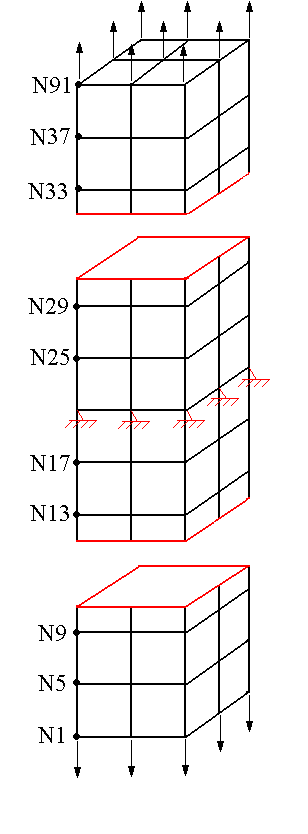
Figure 2.4-1: Final mesh and positioning of the tested nodes
Identification |
Reference |
Tolerance |
DXpour all nodes just below the lower interface |
0.00 |
1.0E-15 |
DXpour all nodes just above the lower interface |
0.00 |
1.0E-15 |
DYpour all nodes just below the lower interface |
0.00 |
1.0E-15 |
DYpour all nodes just above the lower interface |
0.00 |
1.0E-15 |
DZpour all nodes just below the lower interface |
-3.E-3 |
1.0E -09% |
DZ for all nodes just above the lower interface |
0.00 |
1.0E-15 |
DXpour all nodes just below the top interface |
0.00 |
1.0E-15 |
DXpour all nodes just above the top interface |
0.00 |
1.0E-15 |
DYpour all nodes just below the top interface |
0.00 |
1.0E-15 |
DYpour all nodes just above the top interface |
0.00 |
1.0E-15 |
DZpour all nodes just below the top interface |
0.00 |
1.0E-15 |
DZpour all nodes just above the top interface |
3.E-3 |
1.0E -09% |
To test all the nodes at once, we test the minimum and the maximum of the column.
2.5. notes#
It is noted that the values of the degrees of freedom tested are those expected, the interfaces open thus separating the bar into three parts. The result is visualized using post-processing operators.