4. C modeling — Inclined interfaces#
The purpose of this modeling is to prove that friction contact is taken into account for inclined interfaces as well as the correct functioning of the cutting and post-processing algorithms.
An angle of inclination \(\theta \mathrm{=}30°\) was chosen according to the rotation around the axis \(\mathit{OX}\), for the two interfaces. The normal to the interfaces created in this way is noted \(\mathrm{n}\) and the tangent vector is noted \(\tau\):
\(\mathrm{n}\mathrm{=}(\begin{array}{c}0\\ \mathrm{-}1\mathrm{/}2\\ \sqrt{3}\mathrm{/}2\end{array}),\tau \mathrm{=}(\begin{array}{c}0\\ \sqrt{3}\mathrm{/}2\\ 1\mathrm{/}2\end{array})\) eq 6-1
The new level functions introducing the two cracks in the command file are:
\(\text{LN1}\mathrm{=}\text{Z}\mathrm{-}\text{tan}\theta \mathrm{\cdot }Y\mathrm{-}(\text{LZ}\mathrm{/}4\mathrm{-}\text{tan}\theta \mathrm{\cdot }\text{LX}\mathrm{/}2)\) eq 6-2
\(\text{LN2}\mathrm{=}\text{Z}\mathrm{-}\text{tan}\theta \mathrm{\cdot }Y\mathrm{-}(3\mathrm{\cdot }\text{LZ}\mathrm{/}4\mathrm{-}\text{tan}\theta \mathrm{\cdot }\text{LX}\mathrm{/}2)\) eq 6-3
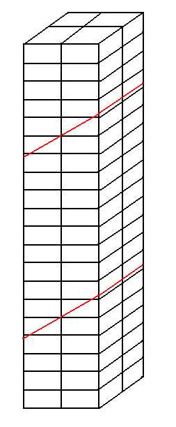
4.1. Figure 4.1-1: Meshing for mesh modeling CCaractéristiques#
Compared to models A and B, the number of elements in the direction \(Z\) (height of the bar) has been multiplied by 2 in order to avoid the contiguity of the elements enriched by the two inclined interfaces. So we have a mesh \(2\mathrm{\times }2\mathrm{\times }20\) HEXA8 elements (see []).
4.2. Boundary conditions#
The boundary conditions make it possible to perform a mixed load: compression at the level of the first interface and traction for the second.
Thus, in addition to embedding the nodes belonging to the median surface (as for the first two models), positive displacements in the \(Z\) direction are imposed for the nodes belonging to the extreme surfaces (lower and upper). So we will have:
GROUP_NO = SURFMED: DX = 0, DY = 0, and DZ = 0
GROUP_NO = SURFINF: DX = 0, DY = 0, and DZ = DEPZ
GROUP_NO = SURFSUP: DX = 0, DY = 0, and DZ = DEPZ
4.3. Analytical resolution#
The analytical solution concerns, for the lower block (interface 1), the values of contact pressure and friction semi-multipliers. For the upper block (interface 2), the analytical solution concerns the displacement values of the nodes. The solution for the latter is identical to that of modeling A and therefore we will only detail the analytical solution for the lower block.
Since the interfaces are inclined, there may be slippage. To avoid this, adhesion is forced by choosing a sufficiently high Coulomb coefficient of friction. Theoretically, all you need to do is take:
\(\mu >\text{tan}(\theta )\) eq 6.3-1
Thus, the solution of the problem remains the same as the solution of the same problem without an interface. The analytical resolution for this problem is presented in [V604182 - §4.1]. For contact pressure, we find:
\(\lambda \mathrm{=}{n}_{z}\mathrm{\cdot }E\frac{\text{DEPZ}}{\text{LZ}\mathrm{/}2}\mathrm{\cdot }{n}_{z}\) eq 6.3-2
and for friction semi-multipliers:
\(\Lambda \mathrm{=}(\frac{1}{\mu }\frac{{\tau }_{z}}{{n}_{z}})\tau\) eq 6.3-3
With the numerical values previously introduced and considering \(\mu \mathrm{=}1\), \(\lambda \mathrm{=}\mathrm{-}{9.10}^{3}\mathit{Pa}\) is obtained for the contact pressure and for the friction semi-multiplier in the direction \(\tau\), \(\Lambda \mathrm{\cdot }\tau \mathrm{=}1\mathrm{/}\sqrt{3}\).
4.4. Tested sizes and results#
The values of the contact pressure and of the friction semi-multipliers for interface 1 are tested. For interface 2, we test the values of the movements above and below the level-set.
Identification |
Reference |
DXpour all nodes just below the lower interface |
0.00 |
DXpour all nodes just above the lower interface |
0.00 |
DYpour all nodes just below the lower interface |
0.00 |
DYpour all nodes just above the lower interface |
0.00 |
LAGS_Cpour all nodes in the lower interface |
-9E3 |
LAGS_F1pour all nodes in the lower interface |
0 |
LAGS_F2pour all nodes in the lower interface |
\(1\mathrm{/}\sqrt{3}\) |
DXpour all nodes just below the top interface |
0.00 |
DXpour all nodes just above the top interface |
0.00 |
DYpour all nodes just below the top interface |
0.00 |
DYpour all nodes just above the top interface |
0.00 |
DZpour all nodes just below the top interface |
0.00 |
DZpour all nodes just above the top interface |
3.0E-3 |
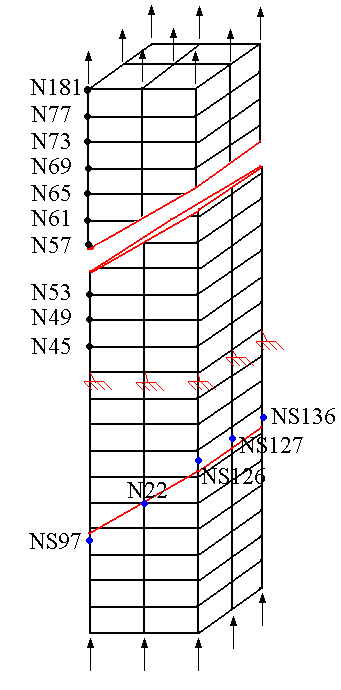
Figure 4.4-1: Final mesh and positioning of the tested nodes
To test all the nodes at once, we test the minimum and the maximum of the column.
4.5. notes#
It is verified that the numerical values obtained for the degrees of freedom tested, following the analysis with several X- FEM interfaces, are indeed identical with the values of the analytical solution for the two interfaces.