1. Reference problem#
1.1. Structure geometry#
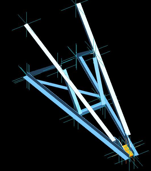
We’re looking at console MEKELEC. It is a P4T pylon console, whose dimensions have been reduced to facilitate test instrumentation while maintaining a structure whose failure modes can be varied and cover those encountered in a real truss tower.
The structure is composed of 10 angles assembled on their wings with bolts, or by means of gussets. You can refer to [3] for detailed plans of the console.
1.2. Characteristics of the angles used#
The angles used in console MEKELEC are standard profiles in metal construction. The base unit for the quantities below is meters.
Beams |
\(\mathit{AE45}\mathrm{\times }3\) |
|
|
|
\(A\) |
2.638081e-04 |
3.077706e-04 |
2.344277e-04 |
2.344277e-04 |
\(\mathit{IY}\) |
8.013486e-08 |
7.077171e-08 |
4.210543e-08 |
4.210543e-08 |
\(\mathit{IZ}\) |
2.087844e-08 |
1.855685e-08 |
1.095197e-08 |
1.095197e-08 |
\(\mathit{AY}\) |
2.419087e+00 |
2.394947e+00 |
2.359465e+00 |
2.359465e+00 |
\(\mathit{AZ}\) |
2.207830e+00 |
2.118989e+00 |
2.163107e+00 |
2.163107e+00 |
\(\mathit{JX}\) |
8.404596e-10 |
1.784041e-09 |
9.865361e-10 |
|
\(\mathit{JG}\) |
1.243656e-13 |
1.871860e-13 |
8.685007e-14 |
|
\(\mathit{EY}\) |
1.459718e-02 |
1.233794e-02 |
1.108092e-02 |
1.108092e-02 |
\(\mathit{IYR2}\) |
6.307966e-10 |
4.829759e-10 |
2.482771e-10 |
2.482771e-10 |
The sizes \(\mathit{EZ}\) and \(\mathit{IZR2}\) are zero for all the beams.
1.3. Material properties#
Only one material is used, it is \(\mathit{E24}\) steel. During tests preliminary to the tests, the real characteristics of the steel used could be measured, making it possible to adapt the values of the various material parameters. Below are the characteristics used in the calculation:
\(E\mathrm{=}210000\mathit{MPa}\) |
\(\nu \mathrm{=}0.3\) |
\({\sigma }_{e}\mathrm{=}300\mathit{Mpa}\) |
\({E}_{t}\mathrm{=}1000\mathit{Mpa}\) |
1.4. Boundary conditions and loading#
Boundary conditions are imposed at points \(A\), \(B\), \(C\), \(D\): \(\mathit{DX}\mathrm{=}\mathit{DY}\mathrm{=}\mathit{DZ}\mathrm{=}\mathit{DRX}\mathrm{=}\mathit{DRY}\mathrm{=}0\) To simulate the flexibility of the folded gussets used at the attachment points, we leave the rotation around \(Z\) free. |
|
Three types of loading cases are possible (cf. figure for points \(P\) and \(Q\)): \(\mathit{C1}\): \(\mathit{FZ}\mathrm{=}1\text{.}0\mathrm{\times }t\) in \(P\) \(\mathit{C2}\): \(\mathit{FZ}\mathrm{=}\mathrm{-}1\text{.}0\mathrm{\times }t\) in \(P\) \(\mathit{C3}\): \(\mathit{FY}\mathrm{=}1\text{.}0\mathrm{\times }t\) in \(Q\) |
Note: the aim of the test case here is to determine the pseudo-time \(t\) corresponding to the ruin, i.e. the maximum force allowed by the structure. It is a horizontal tangent in the response of the structure (force-displacement curve at the point of application of the force).