4. B modeling#
4.1. Characteristics of modeling#
Modeling POU_D_TGM (140 elements)/DIS_TR (22 elements)
F
P
D
C
A
B
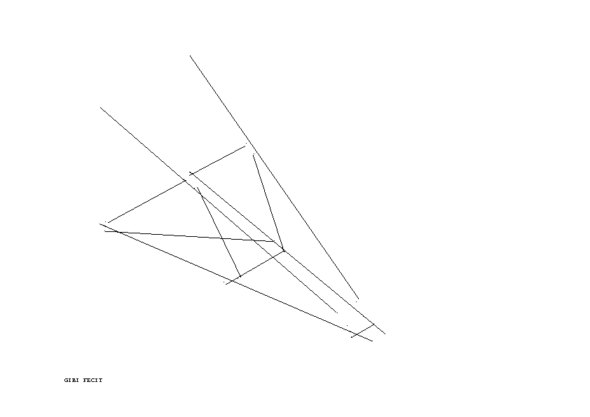
The modeling of bolted assemblies is provided by discretes whose stiffness is fixed in a fixed manner. The eccentricities of the attachment points are taken into account (which explains why the elements are not concurrent). The model is obtained from the pre-processor EVEREST.
The load case is the second (\(\mathit{C2}\)).
4.2. Characteristics of the mesh#
Number of knots: 191
Number of meshes and types: 162 SEG2 (including 22 of zero length for discrete ones)
4.3. Characteristics of the cross section (fibers)#
Number of fibers: 40 (divided into 2 in the thickness and into 10 in the length of the wings)
4.4. Tested sizes and results#
4.4.1. Tested values#
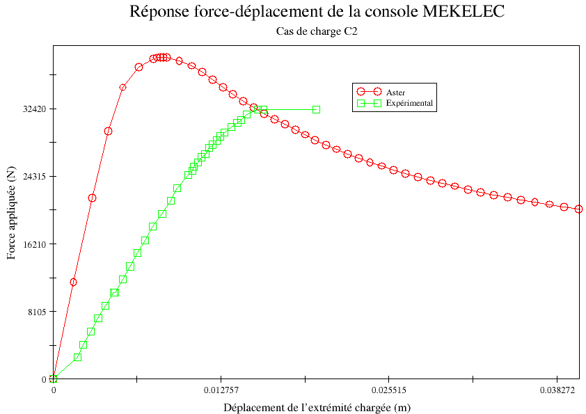
The value tested is the estimated ruin load for the structure. Since the reference results are experimental, comparisons are combined with non-regression tests. The ruin load for the design is defined as being the maximum value taken by the force applied to the structure.
The injective nature of the force-displacement curve gives us the possibility of testing it in non-regression for the various values of parameter ETA_PILOTAGE.
Reminder: we pilot the structure in arc length, so we observe a softening.
Load case |
Reference |
Reference type |
Tolerance |
C2 |
32.4 |
“SOURCE_EXTERNE” |
30% |
4.4.2. Graphical results of B modeling#
4.4.3. notes#
The numerical response of the structure is obtained by controlling the entire structure in arc-length, this makes it possible to observe the softening due to the ruin and therefore to be able to test the maximum value of the control state (parameter ETA_PILOTAGE).
The ruin load for this load case is overestimated by 20%. Again, the rigidity of the structure is too great compared to the real model: the gussets that make it possible to ensure the assemblies at the head and foot of the console are supposed to behave rigidly when they are plates.
Unlike the previous modeling, this has the effect of giving an erroneous limit load. In fact, the tests have shown the importance of geometric non-linearities (ruin by elasto-plastic buckling of the angles of the upper panel), there is no redistribution of forces following plastification, the ruin is sudden. The softening is concomitant with the end of the elastic slope.
4.4.4. Comparison of the modes of ruin#
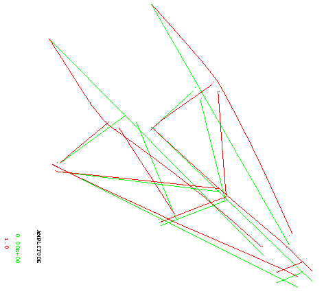
Figure 4.4.4-a : Ruin mode predicted by the calculation in C2 configuration (amplitude 1)
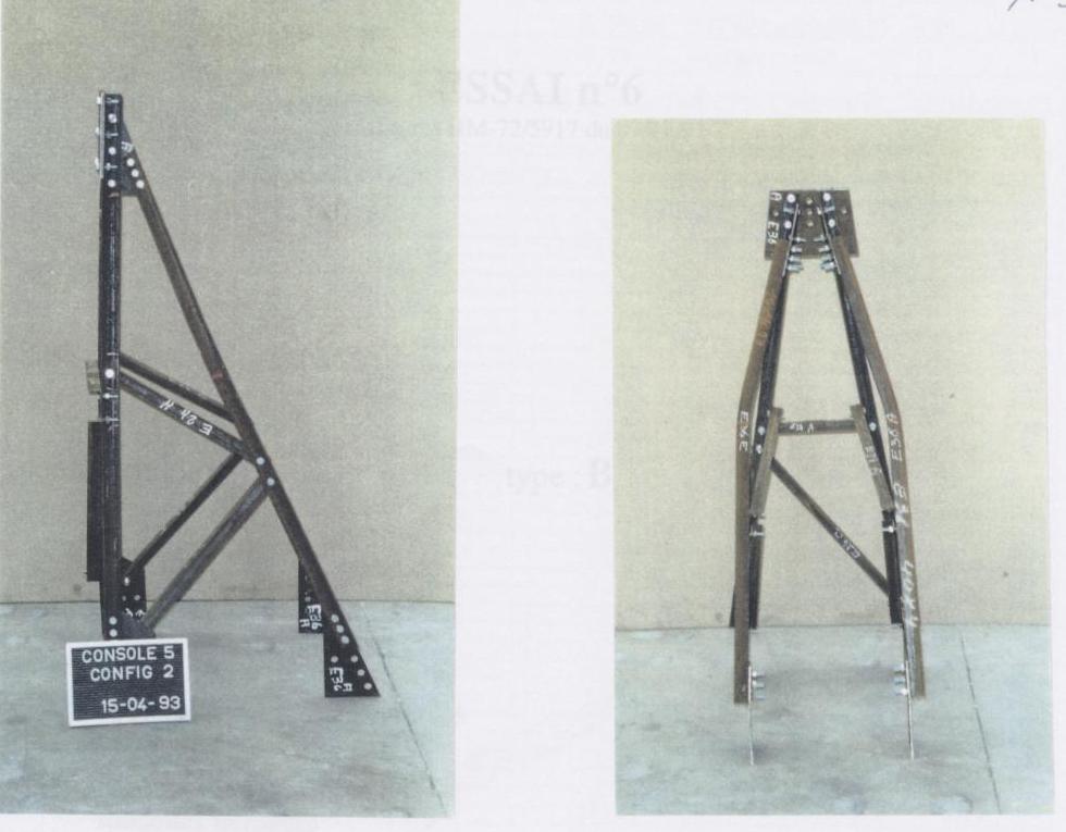
Figure 4.4.4-b : Failure mode observed during tests in C2 configuration