1. Reference problem#
1.1. Geometry#
We consider a rectangular plate with the following dimensions:
\(B=30\mathit{cm}\) thickness
length \(H=3m\)
height \(L=12m\)
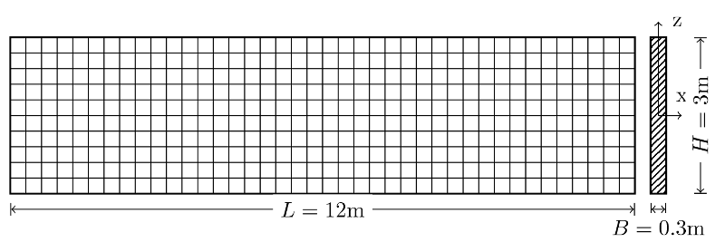
Figure 1. Geometry of the rectangular plate.
1.2. Material properties#
Concrete is isotropic elastic with the following material properties:
\(E=30000N/{\mathit{mm}}^{2}\)
\(\nu =0.3\)
For the calculation of reinforcement (in Eurocode 2), the following set of properties will be considered:
Bottom and top coating \({c}_{\mathit{inf}}={c}_{\text{sup}}=20\mathit{mm}\)
Characteristic compressive strength of concrete \({f}_{\mathit{ck}}=35\mathit{MPa}\)
Work hardening limit characteristic of \({f}_{\mathit{yk}}=450\mathit{MPa}\) steel
Chart type (sant-e): “B1”
Steel safety factor at ELU (Fundamental and Accidental) \({\mathrm{\gamma }}_{s}=\mathrm{1,15}\)
Concrete Safety Coefficient at ELU (Fundamental and Accidental) \({\mathrm{\gamma }}_{c}=\mathrm{1,5}\)
Boundary stress of concrete at ELS Characteristic \({\mathrm{\sigma }}_{\text{c,lim}}=\mathrm{1,0}\times 35=35\mathit{MPa}\)
Boundary stress of steel at ELS Characteristic \({\mathrm{\sigma }}_{\text{s,lim}}=\mathrm{1,0}\times 450=450\mathit{MPa}\)
Boundary stress of concrete at the ELS Quasi-Permanent \({\mathrm{\sigma }}_{\text{c,lim,qp}}=\mathrm{1,0}\times 35=35\mathit{MPa}\)
Steel-concrete equivalence coefficient to ELS \({\mathrm{\alpha }}_{E}=\mathrm{15,0}\)
Steel class: “B”/\({\mathrm{\alpha }}_{\mathit{cc}}=\mathrm{1,0}\)
\(\mathit{FERR}\text{\_}\mathit{SYME}=\text{'}\mathit{NON}\text{'}\)/\(\mathit{FERR}\text{\_}\mathit{COMP}=\text{'}\mathit{OUI}\text{'}\)/\(\mathit{EPURE}\text{\_}\mathit{CISA}=\text{'}\mathit{NON}\text{'}\)/\(\mathit{FERR}\text{\_}\mathit{MIN}=\text{'}\mathit{NON}\text{'}\)
Density of \({\mathrm{\rho }}_{\mathit{acier}}=7800\mathit{kg}/{m}^{3}\) steel
Maximum crack opening allowed on the underside of ELS QP \({w}_{\text{max,inf}}=\mathrm{0,25}\mathit{mm}\)
Maximum crack opening allowed on the upper side of ELS QP \({w}_{\text{max,sup}}=\mathrm{0,3}\mathit{mm}\)
Load time coefficient for calculation at ELS QP \({K}_{T}=\mathrm{0,4}\)
Diameter of the bars following “X” for calculation in ELS QP \({\mathrm{\varphi }}_{X}=\mathrm{20,0}\mathit{mm}\)
Diameter of the bars following “Y” for calculation in ELS QP \({\mathrm{\varphi }}_{Y}=\mathrm{25,0}\mathit{mm}\)
1.3. Boundary conditions and loads#
The plate is loaded in its plane by a shear force \({F}_{Z}=-\mathrm{1,5}\cdot {10}^{6}N\) in the first load case (nodal load « Shearld1 » in the command file). This load case will be tested at ELS QUASI PERMANENT.
A second load case (nodal load « Shearld2 » in the command file) is obtained by applying twice this force, i.e. \({F}_{Z}=-3\cdot {10}^{6}N\). This load case will be tested at ELS CARACTERISTIQUE.
A third load case (nodal load « Shearld3 » in the command file) is obtained by applying triple this force, i.e. \({F}_{Z}=-\mathrm{4,5}\cdot {10}^{6}N\). This load case will be tested at ELU.
The plate is then loaded into its plane by a \({F}_{Y}=1\cdot {10}^{6}N\) traction force ( »tractLD1 » node loading in the command file). This load case will be tested at ELS QUASI PERMANENT.
A second load case (nodal load « tractLD2 » in the command file) is obtained by applying twice this force, i.e. \({F}_{Y}=2\cdot {10}^{6}N\). This load case will be tested at ELS CARACTERISTIQUE.
A third load case (nodal load « tractLD3 » in the command file) is obtained by applying triple this force, i.e. \({F}_{Y}=3\cdot {10}^{6}N\). This load case will be tested at ELU.
The plate is finally loaded in its plane by a compression force \({F}_{Y}=-\mathrm{1,5}\cdot {10}^{6}N\) in a seventh load case ( »ComprLD1 » node loading in the command file). This load case will be tested at ELS CARACTERISTIQUE.
A last load case (nodal load « ComprLD2 » in the command file) is obtained by applying twice this force, i.e. \({F}_{Y}=-3\cdot {10}^{6}N\). This load case will be tested at ELU.
The plate is embedded on the left side, at the opposite end of the point of application of the force (); thus, all degrees of freedom are set to zero.
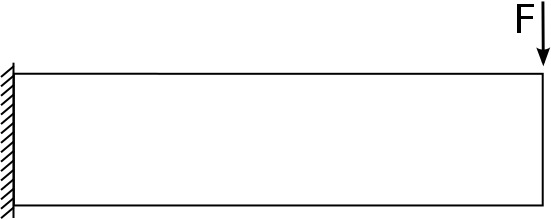
Figure 2. Blocking and loading for “ShearlD” cases
1.4. Initial conditions#
The structure is initially at rest.