1. Reference problem#
1.1. Geometry#
We consider a reinforced concrete plate, comprising reinforcement plies on the lower and upper faces. This plate is embedded at one end, and subjected to a moment at the other end.
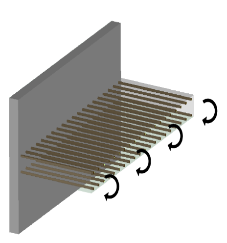
Figure 1: Classic problem of flexure of a reinforced concrete plate.
To limit the calculation cost, only one section of a plate is modelled, at the edges of which periodicity conditions are imposed. The dimensions of the plate and the frames are shown in Figure.
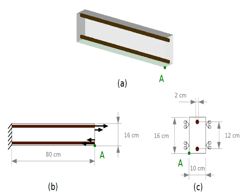
Figure 2: Dimensions of the modelled plate section. (a) General view; (b) longitudinal view; (c) section of the modelled section.
The reinforcement sheets are represented by an equivalent grid or membrane model, which makes it possible to greatly limit the calculation cost (see Figure). Points POINT_1 and POINT_2 are used for post-processing the results.
Figure 3: Representation of reinforcement sheets by an equivalent grid or membrane model
1.2. Material properties#
Concrete has an isotropic homogeneous elastic behavior, characterized by the Young’s modulus and the Poisson’s ratio shown below:
\(\mathrm{\{}\begin{array}{c}{E}_{B}\mathrm{=}30\text{GPa}\\ {\nu }_{B}\mathrm{=}0.22\end{array}\)
Steel also has an isotropic homogeneous elastic behavior, characterized by the coefficients:
\(\mathrm{\{}\begin{array}{c}{E}_{A}\mathrm{=}200\text{GPa}\\ {\nu }_{A}\mathrm{=}0.3\end{array}\)
1.3. Boundary conditions and loads#
The boundary conditions applied to the plate are indicated below, corresponding respectively to the embedment conditions, to the periodicity conditions and to the moment exerted at the end of the plate:
\(\mathrm{\{}\begin{array}{c}u\mathrm{=}0\text{sur}\text{ENCAST}\\ {u}_{Y}\mathrm{=}0\text{sur}\text{BORDS}\\ {F}_{X}\mathrm{=}937500\frac{Z\mathrm{-}0.08}{0.08}\text{sur}\text{BOUT}\end{array}\)