2. Modeling A#
2.1. Characteristics of the mesh#
The mesh is quadratic radiating around the crack; it is composed of 27670 knots forming 9519 meshes including 100 triangles allowing deraffination. The meshes are quadratic. « Barsoum » type elements are used at both ends of the crack. The and show the mesh used.
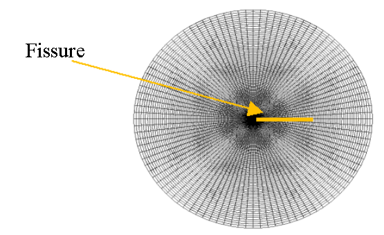
Figure 2.1: Disk mesh.
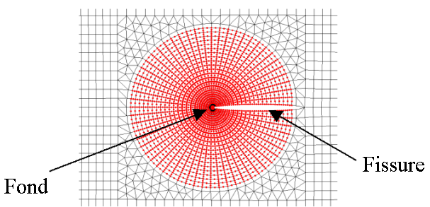
Figure 2.2: Mesh: zoom on the crack.
From the mesh, several crowns are defined which will be used later, during post-treatment in fracture mechanics. Each ring is characterized by the data of a lower radius (R_ INF) and an upper radius (R_ SUP). The correspondence is also given in terms of the number of layers of elements.
Value of R_ INF (mm) |
Value of R_ SUP (mm) |
Correspondence in number of element layers [1] _ |
||
Crown No. 1 |
1.009 |
2.05 |
2h-4h |
|
Crown No. 2 |
2.05 |
4.228 |
4.228 |
4h-8am |
Crown No. 3 |
4,228 |
9,0 |
8h-16h |
2.2. Calculations made#
It should be noted that the principle of this test is to verify the equivalence between taking into account an initial state and an equivalent thermal loading, during post-treatment of fracture mechanics.
The quantities of interest are the energy release rate (G) and the stress intensity factors (limited here to KI because the configuration only requires mode I because of the symmetry). Paragraph § 2.3.1 details the different ways of post-processing these quantities that are used and tested.
Modeling: The configuration is two-dimensional. Mechanical calculations are carried out under the hypothesis of plane deformations.
Reference calculation:
Since the analytical solution is not known, the first step consists in generating the calculation used as a reference: that is to say the linear thermo-elasticity calculation. The creation of the temperature field is followed by the linear thermo-elastic calculation, following which two types of post-treatments are carried out:
post-treatment in fracture mechanics in order to determine the reference values of the quantities of interest,
an extraction of the constraint field, which will serve as the initial constraint field.
Calculation with initial constraints:
An incremental linear elasticity calculation with a given initial state in the form of a field of initial stresses, with the presence of the crack, is carried out. It is important to note that the initial state is filled in via an initial constraints field, and not by the data of a results-type concept (EVOL_NOLI) in the resolution operator.
Then, post-treatments in fracture mechanics are carried out. In order to test the various possibilities offered by the CALC_G command, several configurations are implemented, which differ in the type of initial stress field provided to the CALC_G command: at Gauss points, at nodes by element, or at nodes.
2.3. Tested sizes and results#
2.3.1. Tested sizes#
We test the values of the energy return rate (G) derived from:
operator CALC_G, option G.
We also test the values of the stress intensity factor in mode I (KI) derived from:
operator CALC_G, option K,
operator POST_K1_K2_K3.
For post-treatments with operator CALC_G, the 3 crowns previously defined are systematically tested.
Finally, the values obtained from the reference calculation were compared each time with the values obtained from the calculation with initial state, under iso-condition (same representation of the initial stress field, same post-processing operator, same crown).
2.3.2. Results#
Energy return rate test (without special mention, G refers to the G resulting from the calculation with initial state):
Identification |
Reference |
Reference type |
Tolerance |
|
CALC_G/G |
||||
\(G\) from thermal calculation (reference), crown No. 3 |
“NON_REGRESSION” |
“” |
||
\(G\) with initial state defined at Gauss points, crown no. 1 |
55,3629 |
“AUTRE_ASTER” |
0.01% |
|
\(G\) with initial state defined at Gauss points, crown #2 |
55.3649 |
“AUTRE_ASTER” |
0.01% |
|
\(G\) with initial state defined at Gauss points, crown #3 |
55.3651 |
“AUTRE_ASTER” |
0.01% |
|
\(G\) with initial state set to nodes by element, crown #1 |
55,3629 |
“AUTRE_ASTER” |
0.0% |
|
\(G\) with initial state set to nodes by element, crown #2 |
55.3649 |
“AUTRE_ASTER” |
0.01% |
|
\(G\) with initial state set to nodes by element, crown #3 |
55,3651 |
“AUTRE_ASTER” |
0.01% |
|
\(G\) with initial state set at the nodes, crown #1 |
55.3629 |
“AUTRE_ASTER” |
0.01% |
|
\(G\) with initial state set at the nodes, crown #2 |
55.3649 |
“AUTRE_ASTER” |
0.01% |
|
\(G\) with initial state set at the nodes, crown #3 |
55,3651 |
“AUTRE_ASTER” |
0.01% |
Stress Intensity Factors Test:
Identification |
Reference |
Reference type |
Tolerance |
|
CALC_G/K |
||||
\({K}_{I}\) from thermal calculation (reference), crown No. 3 |
“NON_REGRESSION” |
“” |
||
\({K}_{I}\) with initial state defined at Gauss points, crown no. 1 |
3574, 36 |
“AUTRE_ASTER” |
0.005% |
|
\({K}_{I}\) with initial state defined at Gauss points, crown #2 |
3574, 43 |
“AUTRE_ASTER” |
0.005% |
|
\({K}_{I}\) with initial state defined at Gauss points, crown #3 |
3574, 44 |
“AUTRE_ASTER” |
0.005% |
|
\({K}_{I}\) with initial state set to nodes by element, crown #1 |
3574, 36 |
“AUTRE_ASTER” |
0.005% |
|
\({K}_{I}\) with initial state set to nodes by element, crown #2 |
3574, 43 |
“AUTRE_ASTER” |
0.005% |
|
\({K}_{I}\) with initial state set to nodes by element, crown #3 |
3574, 44 |
“AUTRE_ASTER” |
0.005% |
|
\({K}_{I}\) with initial state set at the nodes, crown #1 |
3574, 36 |
“AUTRE_ASTER” |
0.005% |
|
\({K}_{I}\) with initial state set at the nodes, crown #2 |
3574, 43 |
“AUTRE_ASTER” |
0.005% |
|
\({K}_{I}\) with initial state set at the nodes, crown #3 |
3574, 44 |
“AUTRE_ASTER” |
0.005% |
Identification |
Reference |
Reference type |
Toleranc e |
POST_K1_K2_K3 |
|||
\({K}_{I}\) from thermal calculation (reference) |
“NON_REGRESSION” |
||
\({K}_{I}\) with initial status |
3576, 75 |
“AUTRE_ASTER” |
0.005% |