3. Modeling A#
3.1. Characteristics of modeling#
The models POU_D_E, POU_D_T, POU_D_TG, POU_D_EM, and POU_D_TGM are assigned to the mesh in turn.
3.2. Characteristics of the mesh#
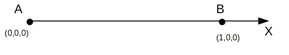
The mesh consists of a SEG2 mesh.
The local coordinate system is identical to the global coordinate system.
3.3. Tested sizes and results#
The values tested are the same regardless of the beam modeling.
3.3.1. Distributed torsional moment#
The load applied in this case obtained by AFFE_CHAR_MECA_F/FORCE_POUTRE /MX or MT.
Node |
Field |
Component |
Reference Value |
Tolerance (%) |
|
A |
REAC_NODA |
|
-1500.0 |
0.1 |
3.3.2. Bending moment distributed along Y#
The load applied in this case obtained by AFFE_CHAR_MECA_F/FORCE_POUTRE /MY or MFY.
It is specified that the node \(B\) is supported according to \(Z\).
Node |
Field |
Component |
Reference Value |
Tolerance (%) |
A |
REAC_NODA |
DZ |
-1625.0 |
0.1 |
A |
REAC_NODA |
|
125.0 |
0.1 |
B |
REAC_NODA |
DZ |
1625.0 |
0.1 |
3.3.3. Bending moment distributed along Z#
The load applied in this case obtained by AFFE_CHAR_MECA_F/FORCE_POUTRE /MZ or MFZ.
It is specified that the node \(B\) is supported according to \(Y\).
Node |
Field |
Component |
Reference Value |
Tolerance (%) |
A |
REAC_NODA |
DY |
1625.0 |
0.1 |
A |
REAC_NODA |
|
125.0 |
0.1 |
B |
REAC_NODA |
DY |
-1625.0 |
0.1 |
3.3.4. Constant bending moment along Y and Z#
The load applied in this case obtained by AFFE_CHAR_MECA/FORCE_POUTRE/MFZ, MZ. MFY, MY, MX, MT.
Next moment \(Z\), node \(B\) is in support according to \(Y\).
Node |
Field |
Component |
Reference Value |
Tolerance (%) |
|
A |
REAC_NODA |
DY |
1000.0 |
0.1 |
|
A |
REAC_NODA |
|
0.0 |
0.1 |
|
B |
REAC_NODA |
DY |
-1000.0 |
0.1 |
Next moment \(Y\), node \(B\) is in support according to \(Z\).
Node |
Field |
Component |
Reference Value |
Tolerance (%) |
|
A |
REAC_NODA |
DZ |
-1000.0 |
0.1 |
|
A |
REAC_NODA |
|
0.0 |
0.1 |
|
B |
REAC_NODA |
DZ |
1000.0 |
0.1 |