1. Reference problem#
1.1. Geometry#
The structure is a plate \(\mathrm{3D}\) of dimensions \(\mathrm{LX}=1m\), \(\mathrm{LY}=10m\) and \(\mathrm{LZ}=30m\), with a flat and horizontal opening crack of length \(a=5m\), located halfway up (see [Figure 1.1‑a]).
To obtain the reference solution, the problem is treated by the classical finite element method and the crack is meshed. On the other hand, for the validation of the modal calculation with the X- FEM method, the crack is not meshed, and the geometry is in fact a healthy plate without cracks. The crack will then be introduced by level sets directly into the command file using the DEFI_FISS_XFEM [U4.82.08] operator.
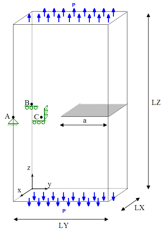
Figure 1.1‑1.1-a: Geometry of the cracked plate with illustration of loading and boundary conditions
We define the points \(\text{A (1,0,15)}\), \(\text{B ( 0,0,15 )}\) and \(\text{C ( 1,3,15 )}\) which will be used to block rigid modes.
1.2. Material properties#
Young’s module: \(E=205000\text{MPa}\)
Poisson’s ratio: \(\nu =0.0\)
Density: \(\rho =7800{\text{kg/m}}^{3}\)
1.3. Boundary conditions and loads#
Boundary conditions are imposed in order to avoid rigid body modes as follows (see Figure 1.1-a):
embedding the node corresponding to point \(A\);
blocking the next move \(Z\) for point \(B\);
blocking of movements following \(Y\) and \(Z\) for point \(C\).
Uniform pressure \(P=\text{10 MPa}\) is applied on the lower and upper sides in order to open the crack in \(I\) mode.